Blower wiring diagrams, Bearing inspection, Periodic lubrication – Rockwell Automation HPK-Series Asynchronous Servo Motor User Manual
Page 14: Grease and repack bearings
14 HPK-Series Asynchronous Servo Motors
Publication HPK-IN001C-EN-P - June 2010
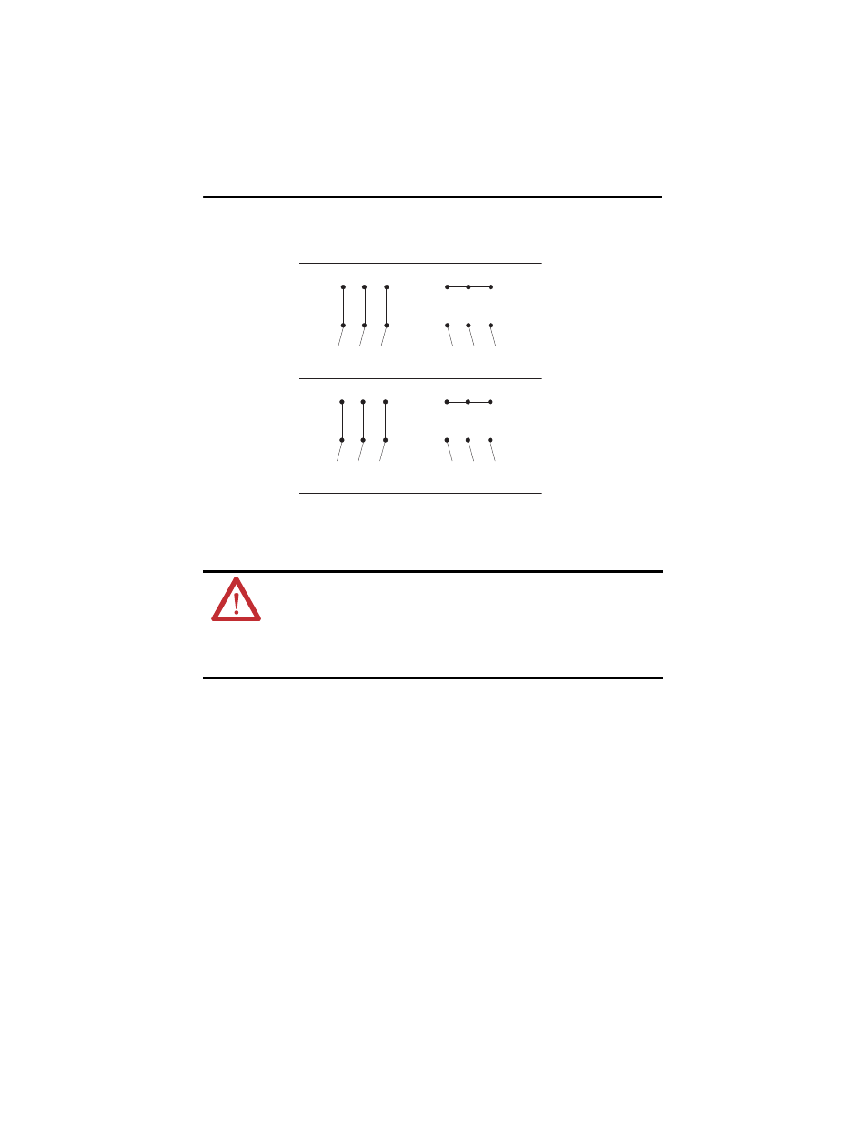
Blower Wiring Diagrams
11.
Attach the feedback cable to the motor as follows:
a. Carefully align the feedback cable connector with the respective motor connector.
b. The flat surface with logo on each connector should align. Do not apply excessive
force when mating the cable and motor connectors. If the connectors do not go
together with light hand force, realign and try again.
c. Fully seat the feedback connector by hand tightening the knurled collar five to six
turns until resistance is felt.
12.
Perform the Troubleshooting and Maintenance procedures listed below that are
appropriate to your installation.
•
Bearing Inspection
•
Periodic Lubrication
•
Grease and Repack Bearings
•
Shaft Key Removal and Installation
ATTENTION: Keyed connectors must be properly aligned and hand-tightened
the recommended number of turns.
Improper connector alignment is indicated by the need for excessive force,
such as the use of tools, to fully seat connectors.
Failure to observe these safety procedures could result in damage to the motor,
cables, and connector components.
DELTA
T4
T6
T5
T2
T1
T3
L2
L1
L3
Low Volts Line
STAR
T4
T6
T5
T2
T1
T3
L2
L1
L3
High Volts Line
U2
W2
V2
V1
U1
W1
L2
L1
L3
Low Volts Line
U2
W2
V2
V1
U1
W1
L2
L1
L3
High Volts Line
U1 = Black
U2 = Green
V1 = Blue
V2 = White
W1 = Brown
W2 = Yellow