Rockwell Automation HPK-Series Asynchronous Servo Motor User Manual
Page 12
12 HPK-Series Asynchronous Servo Motors
Publication HPK-IN001C-EN-P - June 2010
6.
Route power cables into the junction box.
The table lists the access hole diameters for the junction box, and the maximum width of
the wire terminal inside the junction box.
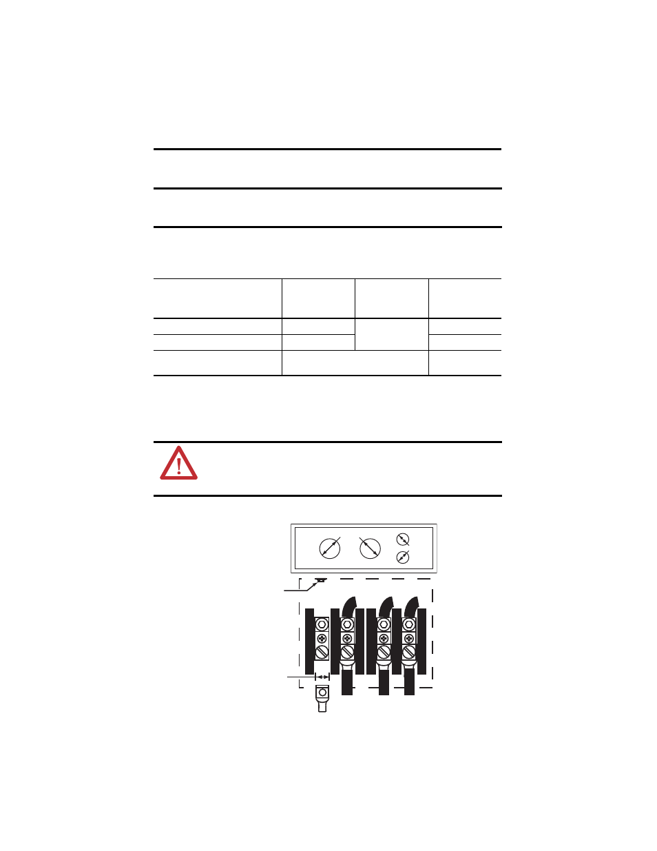
The diagram below depicts the threaded access ports on the HPK-
x13xx and
HPK-
x16xx motors, and the connector block or terminal strip connections.
HPK-x13xx and HPK-x16xx Power Cable Access and Wiring
IMPORTANT
The recommended wire size is based on motor current requirements and
terminal block sizing. Consult your local electrical code before selecting wire
gauge for your application.
Motor Catalog No.
Dia. A, Max.
mm (in.)
Dia. B, Max.
mm (in.)
Wire Terminal
Max Width
mm (in.)
HPK-x1307, HPK-x1308, HPK-x1310
35 (1.4)
21 (0.84)
19 (0.75)
HPK-x1609, HPK-x1611, HPK-x1613
45 (1.8)
20 (0.825)
HPK-x1815, HPK-x2010, HPK-x2212,
HPK-B2510
(1)
(1)
Wire selection and access port sizing are determined and performed by the end user as they are application dependent.
Blank access plate
63.5 (2.5) spacing of
copper bus bars
ATTENTION: Unshielded power connections should not extend beyond the
terminal block body.
Failure to observe these safety procedures could result in damage to the motor,
cables, and connector components.
Dia. A
Dia. B
Ground and Shield
Connect to Lug
Max. Width
of Wire
Terminal
LINE 1
LINE 2
LINE 3
U
V
W To
HPK
Motor
Terminal Blocks
From Input Power
External View of
Junction Box Showing
Access Port Locations
Internal View of
Junction Box Showing
Terminal Block Wiring