Rockwell Automation HPK-Series Asynchronous Servo Motor User Manual
Page 13
HPK-Series Asynchronous Servo Motors 13
Publication HPK-IN001C-EN-P - June 2010
7.
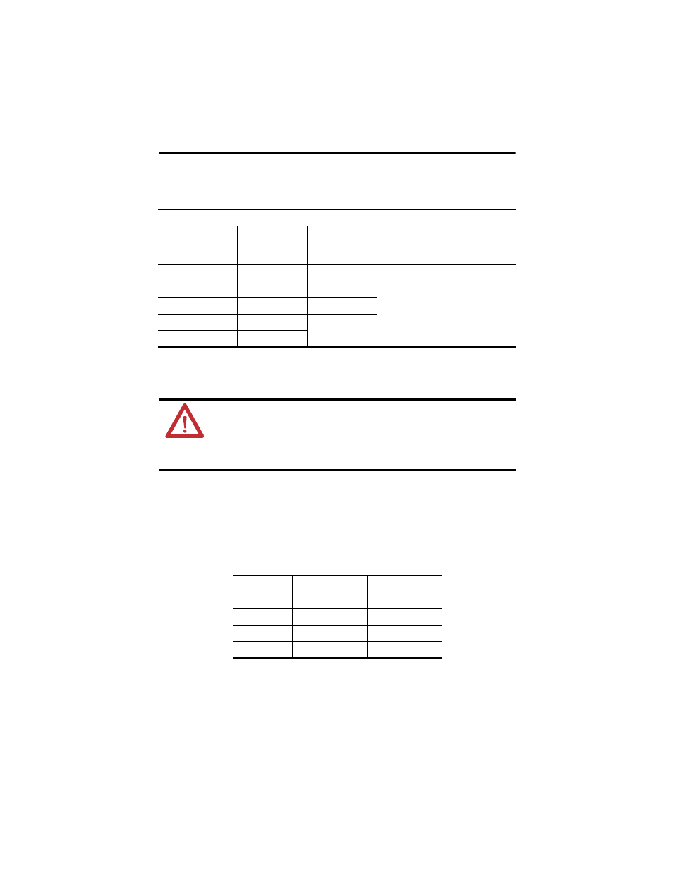
Connect the power cable leads (U/T1, V/T2, and W/T3) to the power terminals.
8.
Connect the ground and shield connect to the ground lug.
9.
Connect the other end of the power cable to the three-phase 380…460V AC power
outputs on the controller as described in the instruction manual for that device.
Proper grounding of power cable shielding is essential for error-free operation. Refer to
the instruction manual of your drive for recommended grounding techniques.
10.
Connect blower leads to the three-phase 380…460V ac power source as outlined in the
table below and shown in the
Blower Wiring Diagrams on page 14
AC Input to Motor
Connect Input
with Wire Color
to Terminal
M8 Clamping
Bolt Torque
M6 Cover
Threaded Bolt
Torque
Line 1
Black
U/T1
14 N•m (1.6 lb-in.)
8 N•m (0.9 lb-in.)
Line 2
Blue
V/T2
Line 3
Brown
W/T3
Ground Green/Yellow
GND
Shield Yellow/Green
ATTENTION: The motor is at line voltage when ac power is connected.
Disconnect and lockout all ungrounded conductors of the ac power line before
attempting any to connect or disconnect power wiring at the motor.
Failure to observe these precautions could result in severe bodily injury or loss
of life.
AC Input to Blower (380…460V)
Connect Input
with Wire Color
to Terminal
Line 1
Black
U
Line 2
Blue
V
Line 3
Brown
W
Ground Green/Yellow
GND