Install the enwatch board, 2 - input, 3 - ground – Rockwell Automation EK-44750C Enwatch Unit User Manual
Page 7
Rockwell Automation Publication GMSI10-IN001A-EN-P - May 2013
Enwatch Unit 7
d. Connect mains input wires, paying attention to terminal markings
live (L) and neutral (N).
e. Verify that all connections are safely made, then replace the yellow
safety cover.
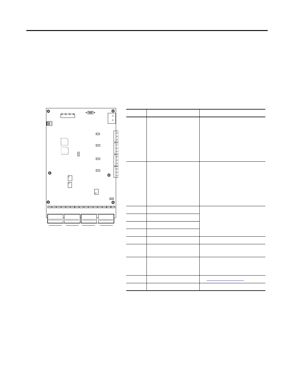
Install the Enwatch Board
Use the following information to install the Enwatch board.
1. Place the Enwatch board on the mounting base-plate standoffs and insert
the screws.
2. Connect the Ethernet cable.
Connector
Description
Pin No./name - Signal
1
Analog input channels 1–8
1 - CH 1 input
2 - CH 1 ground
3 - CH 2 input
4 - CH 2 ground
5 - CH 3 input
6 - CH 3 ground
7 - CH 4 input
8 - CH 4 ground
9 - CH 5 input
10 - CH 5 ground
11 - CH 6 input
12 - CH 6 ground
13 - CH 7 input
14 - CH 7 ground
15 - CH 8 input
16 - CH 8 ground
2
Analog input channels 9–16
1 - CH 9 input
2 - CH 9 ground
3 - CH 10 input
4 - CH 10 ground
5 - CH 11 input
6 - CH 11 ground
7 - CH 12 input
8 - CH 12 ground
9 - CH 13 input
10 - CH 13 ground
11 - CH 14 input
12 - CH 14 ground
13 - CH 15 input
14 - CH 15 ground
15 - CH 16 input
16 - CH 16 ground
3
External trigger 1 / event 1
1 - Power supply
(2)
2 - Input
(3)
3 - Ground
(2) A supply voltage is available on pin 1 of the connector to power an external trigger device. The voltage is equal to
the voltage of the incoming power supply to the board (on connector J9). The limit on the power supply pin on
each external trigger is limit 50 mA.
(3) The external trigger is compatible with a CMOS/TTL logic level (5 V logic). Alternatively, any voltage input in the
range 5 to 24 V can be accommodated. The trigger can be isolated or non-isolated.
4
External trigger 2 / event 2
5
External trigger 3
6
External trigger 4
7
Ethernet interface
RJ-45
8
Supply voltage
+ (plus) - Positive supply voltage
- (minus) - Common
9
Serial port (RS-232)
(1)
(1) To connect to a host computer, use a null modem 9-pin female to 9-pin female cable.
2 - RXD
3 - TXD
5 - Ground
10
Status Indicators
11…16
Screws
A - B
A - B
A - B
A - B
A - B
A - B
A - B
A - B
A - B
A - B
A - B
A - B
A - B
A - B
A - B
TX
RX
LK
OB
+
_
1 - 2 - 3 - 4 - 5 - 6 - 7 - 8
9-10-11-12-13-14-15-16
1 - 2 - 3 - 4 - 5 - 6 - 7 - 8
9-10-11-12-13-14-15-16
3
3
2
2
1
3
3
2
2
1
3
3
2
2
1
3
3
2
2
1
A - B
7
2
1
3
4
5
6
9
8
10
11
12
13
14
15
16