2 wiring – Rockwell Automation SA3000 High Power Modules User Manual
Page 26
3-2
High Power SA3000 AC Power Modules
3.2
Wiring
System wiring is to be done according to the supplied wiring diagrams (W/Es), which
are application-specific. Sections 3.2.1 through 3.2.3 provide additional information on
fuses and recommended wiring.
3.2.1 Fuses
Fuses are provided to protect the Power Module's DC bus, 115 VAC control power
input lines, and individual IGBT phase modules. See table 3.1 for the fuse values.
3.2.2 Wire Sizes
Input wiring should be sized according to applicable codes to handle the SA3000
Power Module's continuous-rated input current. Output wiring should be sized
according to applicable codes to handle the SA3000 Power Module's continuous-rated
output current. Recommended wire sizes are shown in table 3.2. Terminals should be
tightened to the torque values provided in table 3.3.
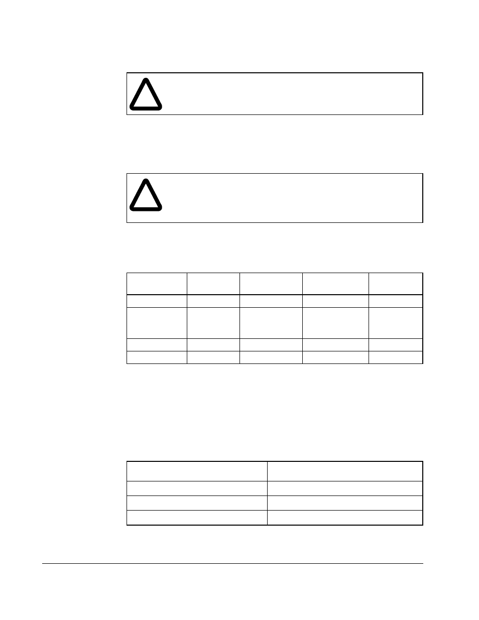
!
ATTENTION: The user is responsible for conforming with all applicable
local, national, and international codes. Failure to observe this precaution
could result in damage to, or destruction of, the equipment.
!
ATTENTION: The NEC/CEC requires that upstream branch circuit
protection be provided to protect input power wiring. Install the fuses
recommended in table 3.1. Do not exceed the fuse ratings. Failure to
observe this precaution could result in damage to, or destruction of the
equipment.
Table 3.1 – Fuse Ratings
Fuse
Circuit
Fuse Current
Rating
Fuse Voltage
Rating
Rockwell
P/N
FPM A,B,C
DC Bus
1000 A
1000 VAC
64676-80P
F103 A,B,C
F104 A,B,C
F105 A,B,C
IGBT Phase
Modules
630 A
1000 VAC
64676-79AZ
1FU
115 VAC
5 A
600 VAC
64676-29R
3FU
115 VAC
3.2 A
600 VAC
64676-29P
Table 3.2 – Recommended DC Bus Input and AC Output Wire Sizes
SA3000 Output Rating
Size of Wire
1
1. NEC-recommended cable types: 40
o
C (104
o
F) copper wire.
534A
2 x 600 Kc Mil (304 mm
2
)
972A
3 x 600 Kc Mil (304 mm
2
)
1457A
4 x 1000 Kc Mil (507 mm
2
)