Figure 2.14 magnet plate installation – Rockwell Automation LC-Series Linear Motor User Manual
Page 22
Item Number 814036 - Rev C
2-16 Installation
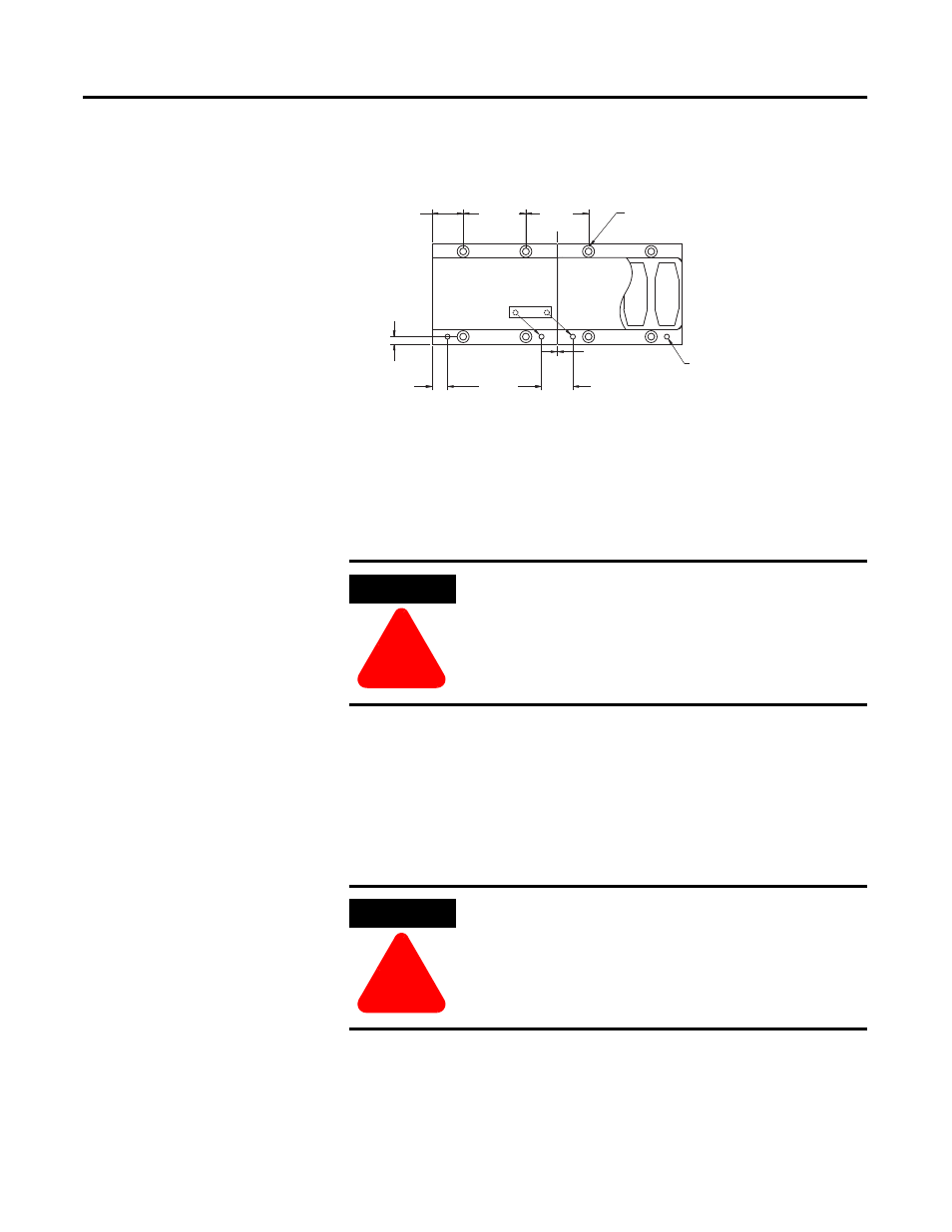
Figure 2.14 Magnet Plate Installation
1. Ensure the mounting surface to which the magnet plate is to be attached
is clear of any and all foreign material. If necessary, stone the mounting
surface (acetone or methanol may be applied as cleaning agent).
2. Verify that the flatness of the surface to which the magnet plate is to be
mounted is 0.005 in. Total Indicator Reading (TIR) per 12.0 inches. This
specification correlates to the overall flatness requirement of 0.005 in.
(.127 mm).
3. Prior to any component installation, verify that the opening for the
magnet plate and coil is dimensioned per Table 2.M.
BUTTING PLATES
BUTTING PLATES
Ø5.50 [0.216] THRU
Ø5.50 [0.216] THRU
C'BORE Ø 9.50 [0.374] X 5.0 [0.197] DP
C'BORE Ø 9.50 [0.374] X 5.0 [0.197] DP
N
N
S
S
25.00
25.00
0.984
0.984
[
[
]
]
50.00
50.00
1.969
1.969
[
[
]
]
12.5
12.5
0.
0.
[
[
]
]
24.8
0.97
[
[
]
]
50.00
50.00
1.969
1.969
[
[
]
]
REF.
REF.
0.5
0.5
0.02
0.02
[
[
]
]
6.0
6.0
0.24
0.24
[
[
]
]
HOLES FOR DOWEL PIN
HOLES FOR DOWEL PIN
Ш 3.988
Ш 3.988
+0.007
+0.007
0
0.1570
0.1570
+0.0003
+0.0003
-0.0000
-0.0000
[
]
N
N
S
S
N
N
S
S
N
N
S
S
ALIGNMENT TOOL
ALIGNMENT TOOL
ATTENTION
!
Do not clean the surface using abrasives!
ATTENTION
!
Never try to place the motor coil assembly directly on the
magnet plates. Serious damage may result. Due to magnetic
attraction.