Installation – Rockwell Automation MinPak Plus Local Operator Station Faceplate Kit 14C201-208 User Manual
Page 2
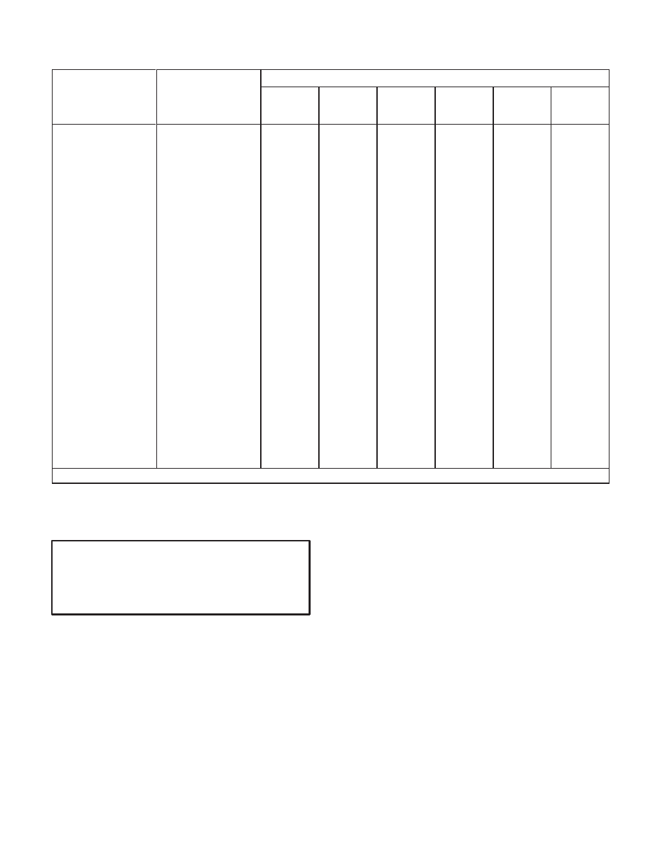
TABLE 1.A
LOCAL OPERATOR'S CONTROL FACEPLATES
When Using a
Specify
Operator's
Functions Provided ➀
When Using a
MinPak Plus
Controller With:
Operator's
Control
Faceplate
Model
Start/
Stop
SpeedĆ
Setting
Pot
TorqueĆ
Setting
Pot
Run/Jog
Selector
Forward/
Reverse
Selector
Automatic/
Manual
Selector
D Blank Faceplate
(Use with Remote
Station)
14C200
no
no
no
no
no
no
D Basic features
14C201
yes
yes
no
yes
no
no
D Basic features plus
armatureĆreversing
14C202
yes
yes
no
yes
yes
no
D Basic features plus
automatic/manual
modes of operation
14C203
yes
yes
no
yes
no
yes
D Basic features plus
armatureĆreversing
and automatic/
manual modes of
operation
14C204
yes
yes
no
yes
yes
yes
D Basic features plus
torque control
14C205
yes
yes
yes
yes
no
no
D Basic features plus
armatureĆreversing
and torque control
14C206
yes
yes
yes
yes
yes
no
D Basic features plus
torque control and
automatic/manual
modes of operation
14C207
yes
yes
yes
yes
no
yes
D Basic features plus
armatureĆreversing,
torque control and
automatic/manual
modes of operation
14C208
yes
yes
yes
yes
yes
yes
➀
POWER ON/OFF circuit breakers standard with Controller.
INSTALLATION
WARNING
BEFORE ATTEMPTING TO INSTALL THIS MINĆ
PAK PLUS MODIFICATION KIT DISCONNECT
AND LOCK OUT ALL SOURCES OF INCOMING
POWER TO THE CONTROLLER.
1. Remove Standard Blank Faceplate from cabinet
door by removing the 8 hex nuts and washers. (ReĆ
fer to Figure 2). NOTE: The Controller ground wire
(green) Isattached to upper hex not to ground
cabinet door. Thismust be returned and reĆ
mounted to thislocation when Local Control StaĆ
tion IsInstalled. (Refer to Figure 3).
2. Clean the area around the circuit breaker boot, on
the Local Control Operators Station that is to be
installed, with alcohol. (Refer to Figure 4).
3. With a sharp knife or razor blade cut a slit on the top
and bottom surfaces of the rubber circuit breaker
boot.
4. Take black plastic cover plate from plastic bag kit
supplied with the Three Phase MinPak Plus and on
back side (side with bump) apply a thin stream of
glue (3/32 max.), from tube of glue supplied with
this kit, around the perimeter of the plate.
5. Turn plastic plate over. Push cut circuit breaker boot
in so that it is totally collapsed and place plastic
plate over hole in operators plate. Hold down or put
weight on top of plastic cover. Hold this way for
three (3) minutes. This allows set time for glue. A toĆ
tal of twelve (12) hours will completely dry the part
to the operators panel. (Refer to Figure 5).