2 wiring – Rockwell Automation SB3000 High Pwr SB3000 AC Pwr Modules (RCS) User Manual
Page 26
3-2
SB3000 Power Modules (RCS)
3.2
Wiring
System wiring is to be done according to the supplied wiring diagrams (W/Es), which
are application-specific. Sections 3.2.1 through 3.2.6 provide additional information on
input fuses, pre-charge components, AC line reactors, and recommended wire types.
3.2.1 Fuses
Fuses are provided to protect the SB3000 Power Module's AC line input, DC bus
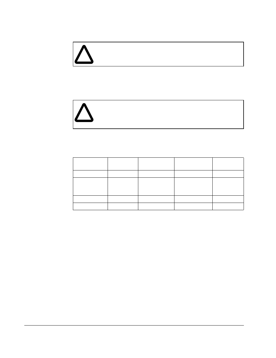
output, and 115V AC input power lines. See table 3.1 for the input fuse values.
3.2.2 Pre-charge Resistors and Fuses
The pre-charge circuit consists of three AC line resistors with an AC contactor bypass.
The pre-charge resistors are protected by fuses in series with each resistor. See
table 3.2. The pre-charge circuit is sized to support the charging of the SB3000 Power
Module’s DC bus capacitors and up to four times the Power Module’s capacitance as a
load. The pre-charge time is 10 seconds or less.
!
ATTENTION: The user is responsible for conforming with all applicable
local, national, and international codes. Failure to observe this precaution
could result in damage to, or destruction of, the equipment.
!
ATTENTION: The NEC/CEC requires that upstream branch circuit
protection be provided to protect input power wiring. Install the fuses
recommended in table 3.1. Do not exceed the fuse ratings. Failure to
observe this precaution could result in damage to, or destruction of the
equipment.
Table 3.1 – Fuse Ratings
Fuse
Circuit
Fuse Current
Rating
Fuse Voltage
Rating
Rockwell
P/N
FPM A,B,C
DC Bus
1000 A
1000 VAC
64676-80P
F103 A,B,C
F104 A,B,C
F105 A,B,C
AC Line
Input
630 A
1000 VAC
64676-79AZ
1FU
115V AC
5 A
600 VAC
64676-29R
3FU
115V AC
3.2 A
600 VAC
64676-29P