Rockwell Automation 36С47 DC Drive Output Contactor Kit 300-500HP User Manual
Page 3
ă9. Using the two furnished 8Ć32 x 1/2" taptite screws,
mount the Fuse Block (49454ĆA) to the left of the
Control Transformer. See Figure 2. The mounting
holes are preĆdrilled in the back panel. Insert the 3.2
amp Fuse (64676Ć1P), 250Ćvolt, UL Class RK5) into the
Fuse Block.
10. Using two furnished 6Ć32 x 1/2" taptite screws, mount
the Relay Socket (600434Ć5R) in the left bay of the
controller as shown in Figure 3. The mounting holes
are preĆdrilled in the back panel. Insert the Relay
(600434Ć6R) into the Relay Socket.
11. Remove the outlet air duct (Figure 3) by loosening the
nine hex head cap screws. Set aside for later
reĆinstallation.
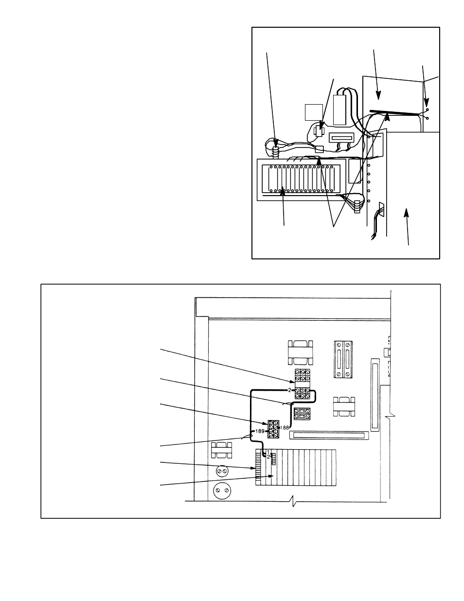
12. Remove the factoryĆinstalled wiring between terminals
43 and 53 on TB1 and terminals 1 and 2 on the
faceplate of the CSS-* card. See Figure 4.
13. Connect Wire Harness 705337Ć35R. Connect leads
189 and 2 to terminals 1 and 2, respectively, on the
faceplate of the CSS- card. Connect the other end of
lead 189 to the 115Ćvolt terminal board and the other
end of the lead 2 to the Relay. See Figures 3, 4 and 7.
* The fourth letter of this regulator PC board designation indicates a difference in the PC board.
Refer to the specific controller to identify the fourĆletter PC board designation.
Figure 3. Controller left bay components.
115 VOLT
TERMINAL BOARD
RELAY IN
RELAY SOCKET
CSS -*CARD
FACEPLATE
CHANNELS
POWER MODULE
OUTLET AIR
DUCT REMOVED
SIDE WALL
OPENINGS
Figure 4. Connecting Wire Harness 705337Ć35R and Wire Assembly 608809Ć12SA.
* The fourth letter of this regulator PC board designation indicates a difference in the PC board. Refer to the specific controller to identify the fourĆletter PC board designation .
CSS-*CARD
FACEPLATE
WIRE ASSEMBLY
608809Ć12SA
WIRE HARNESS
705337Ć35R
TB1
RELAY
115 VOLT
TERMINAL
BOARD
14. Connect Wire Assembly 608809Ć12SA (labeled 188)
between the 115Ćvolt terminal board and the Relay.
See Figures 4 and 7.
15. Connect Wire Assembly 608809Ć12X (the green
ground wire labeled 289) to the Control Transformer.
Using the remaining 10Ć32 x 1/2" taptite screw,