Sequence of events characteristics, Output driver structure, Figure 3 output driver structure – Rockwell Automation T8480 Trusted TMR Analogue Output Module - 40 Channel User Manual
Page 13: Trusted, Module t8480, Soe and process historian, Their “home” fiu
Trusted
TM
Module T8480
Issue 13 Apr 10
PD-T8480
13
Between the HIU and FIU are a series of optically isolated links for data and power. The data link is
synchronized and monitored for variance. Both FIU and HIU have onboard temperature sensors to
characterize temperature-related problems.
The power supplies for both the HIU and FIU boards are redundant, fully instrumented and testable.
Together these assemblies form a Power Integrity Sub System.
1.8. Sequence of Events Characteristics
The module automatically measures the field voltage and current to determine the state of each output
channel. An event occurs when the output transitions from one state to another. When a channel
changes state, the on-board timer value is recorded. When the TMR Processor next reads data from
the output module, the channel state and real-time clock value are retrieved. The TMR Processor
uses this data to log the state change into the system Sequence of Events (SOE) log. The user may
configure each output to be included in the system SOE log. Full details of SOE are contained in PD-
8013 Trusted
TM
SOE and Process Historian.
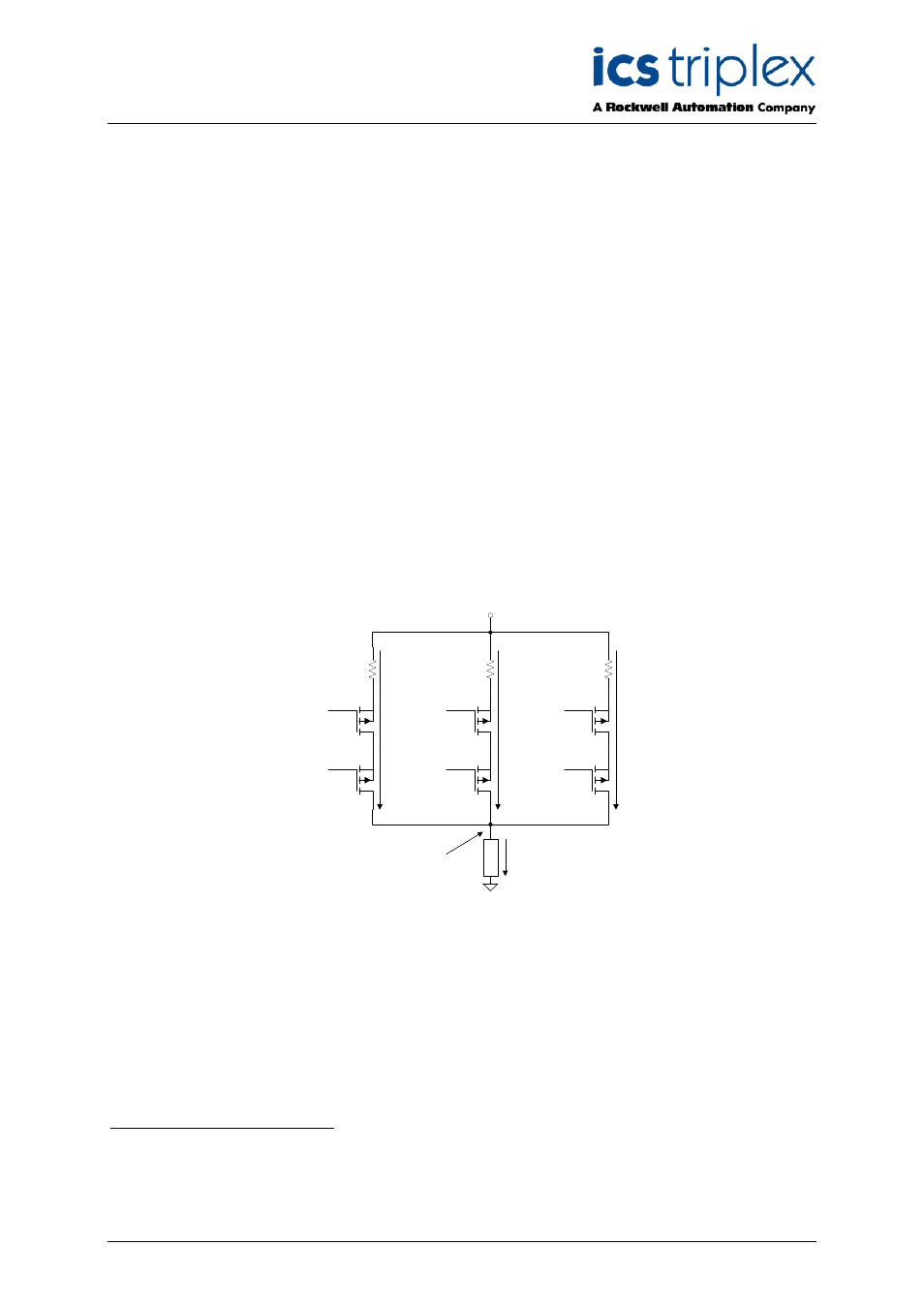
1.9. Output Driver Structure
The Analogue Output Module provides a TMR driver topology where the load is driven by a total of
three fully monitored, fail-safe (6 element) driver channels, one physically resident on each AOFIU in
the module. Any single driver or entire slice failure is designed to leave two of the three fail-safe driver
channels operational to supply regulated current to the load.
TOP_RAIL
PRM_A
PRM_C
PRM_B
ENABLE_C
ENABLE_A
ENABLE_B
LO
A
D
I
LOAD_A
I
LOAD_B
I
LOAD_C
I
LOAD
= I
LOAD_A
+ I
LOAD_B
+ I
LOAD_C
V
FIELD_RTN
R
SENSE_A
R
SENSE_C
R
SENSE_B
V
LOAD
Figure 3 Output Driver Structure
The upper transistors shown in Figure 3 operate in the linear mode, and are controlled by the AOFIU
on which they are physically resident.
The lower switches are N.C. (Normally Closed), and are
controlled by the “upstream” neighbouring FIU.
1
Their “home” FIU.
2
The home FIU, supplies an independent control signal for the “downstream” FIU FSS.