Programming – Rockwell Automation T7408 ICS Regent+Plus DC Digital Input Modules 24VDC, 48VDC and 120VDC User Manual
Page 9
(T7401, 02, and 08) DC Digital Input Modules
P D - 7 0 1 1 M a r - 0 6
9
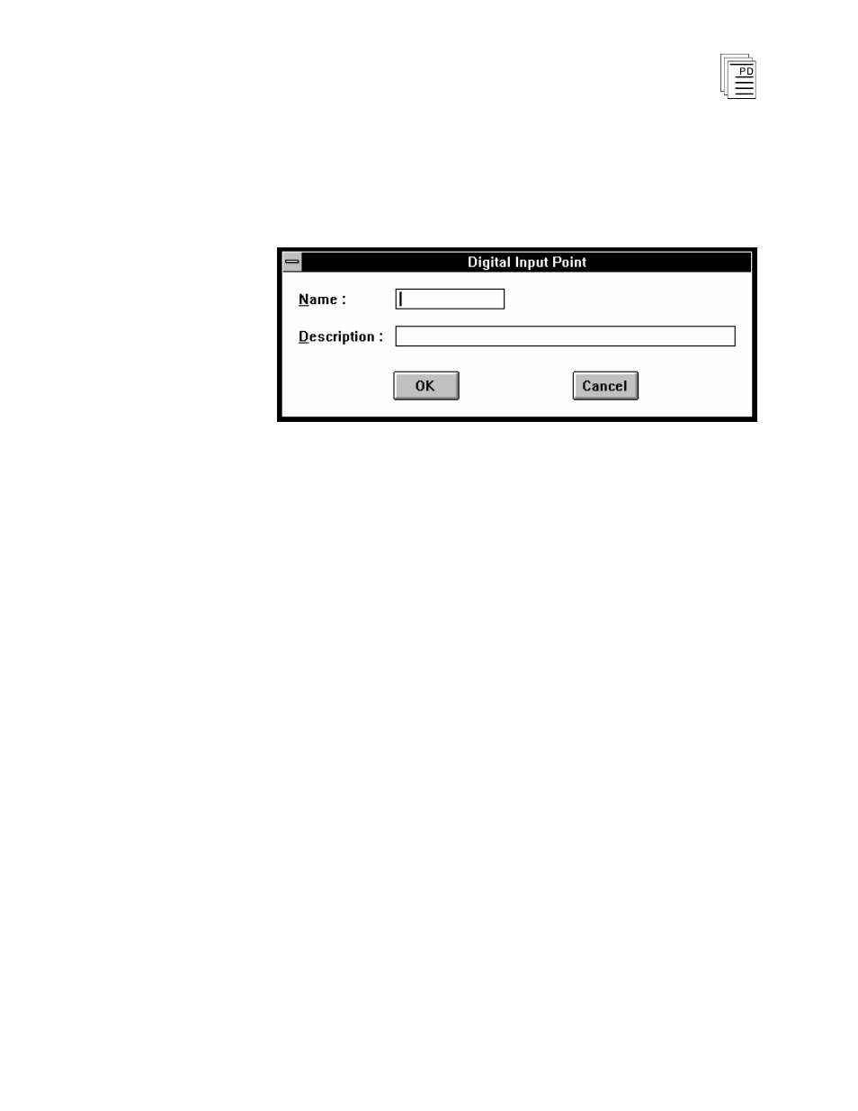
3) Edit each point:
Choose Edit from the Module Definition dialog box to
define a name and description for each I/O point. In the
Digital Input Point dialog, enter a tag name (up to 12
characters) and a description (up to 40 characters).
Figure 7. Defining a Digital Input Point.
The tag names are used in the application program to
represent the input state. In addition, a module tag name can
be entered to represent the combined state of all 16 inputs.
This module tag name represents the 16 inputs as a signed,
16-bit integer. In this format, input point one is the least
significant bit (LSB) and input point 16 is the most significant
bit (MSB).
Programming
Inputs are referenced in the application program through the
tag names defined in the I/O Configuration Editor. When
current flows through the input (field switch closed) the input
is said to be on, or have a value of one. In ladder logic, the on
state would produce power flow in a normally open (N.O.)
contact.
To program fault tolerant configurations using triplicated
digital input modules, a voter element can be used as shown
in Figure 8.