Application, Simplex configuration, Fault tolerant connection – Rockwell Automation T7408 ICS Regent+Plus DC Digital Input Modules 24VDC, 48VDC and 120VDC User Manual
Page 5
(T7401, 02, and 08) DC Digital Input Modules
P D - 7 0 1 1 M a r - 0 6
5
Field Status Indicators
Input status indicators are located on the logic-side (after the
signal conditioning and isolation). The field status indicators
are lit when current is flowing through the input.
Application
Simplex Configuration
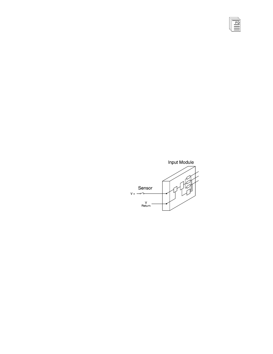
Digital input modules provide a suitable interface to non-
critical input signals. Although many of the circuits in the
digital input modules are automatically tested and
annunciated, some logic circuits and all of the field-side
sensing circuits are simplex and non-tested. This simplex
input configuration is illustrated in Figure 3.
Figure 3. Simplex Digital Input Configuration.
Fault Tolerant Connection
For critical inputs, redundant input modules are used in a
2oo3 or 1oo2 fault tolerant configuration. In these
configurations the redundant input modules are connected to
single or multiple sensors. If redundant sensors are installed
in the field, the redundant modules are connected so that each
sensor connects to one of the redundant modules. These
configurations are illustrated in Figure 4, showing triple
redundant input modules. Each DC digital input module is
hot replaceable. In triple redundant input configurations, if a
fault occurs on one module, it can be removed and replaced