Configuration – Rockwell Automation T7408 ICS Regent+Plus DC Digital Input Modules 24VDC, 48VDC and 120VDC User Manual
Page 8
DC Digital Input Modules (T7401, 02, and 08)
8
I n d u s t r i a l C o n t r o l S e r v i c e s
Table 1. Slot Key Positions.
Module
Upper
Connector
Lower
Connector
T7401
4
15
T7402
10
15
T7408
12
15
Configuration
Each input module is configured using the W
INTERPRET
I/O
Configuration Editor. In the editor, you will perform the
three steps described below to configure the input module.
1) Set the Module Type:
Position the cursor on the module slot you wish to define.
Choose Set Module Type from the Edit Menu and select
the appropriate digital input module from the list.
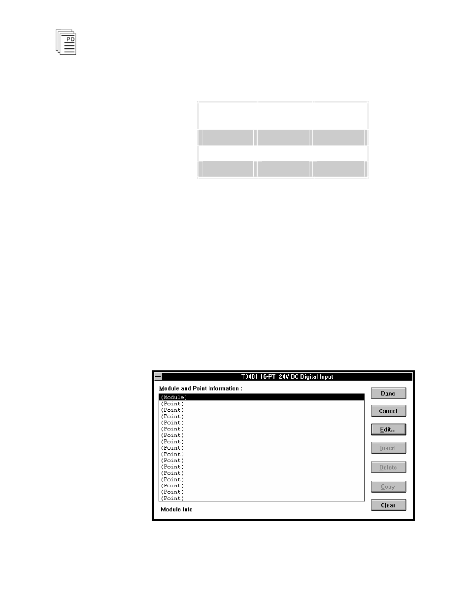
2) Edit the Module Definition:
Choose Edit Module Definition from the Edit Menu. A
dialog box will open where you can define the input point
definitions.
Figure 6. Digital Input Module Definition.