Module operation – Rockwell Automation T7408 ICS Regent+Plus DC Digital Input Modules 24VDC, 48VDC and 120VDC User Manual
Page 2
DC Digital Input Modules (T7401, 02, and 08)
2
I n d u s t r i a l C o n t r o l S e r v i c e s
Module Operation
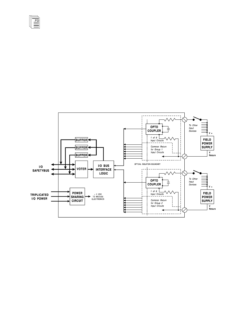
A block diagram of a typical DC digital input module is shown
in Figure 1.
Optical isolation between field wiring and the modules’ logic
circuitry provides field-to-logic isolation — protecting the
modules’ logic circuits from field signal over-voltages,
transients, and other electrical disturbances. It also provides
a safety barrier between the primary field voltages and user
accessible circuits.
Figure 1. Block Diagram of DC Digital Input Module.
When the field switch is closed, the input to the module is on.
When the field switch opens, the input to the module turns off.
Data from the logic side of the optical isolators are bused to
the I/O bus interface logic.
The processor modules send triplicated read data requests to
the input module over the I/O Safetybus. The processors’
addressing data and data read requests are voted by the