2 module replacement – Rockwell Automation 57C423 Common Memory Module User Manual
Page 14
3Ć2
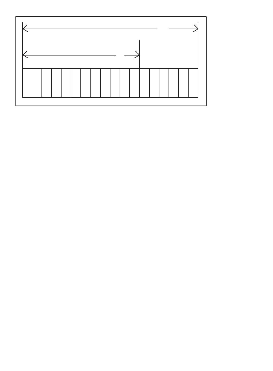
P/S
0
1
2
3
4
5
6
7
8
9 10 11 12 13 14 15
10
Typical 10 Slot Rack
16
Typical 16 Slot Rack
Figure 3.1Ć Rack Slot Numbers
Step 5.
Turn on power to the rack.
Step 6.
Verify the installation. If the Common Memory module was
placed in slot 0, the powerĆup diagnostics performed
automatically by a Processor module should verify that the
module is operational.
If the Common Memory module is placed in any even slot
other than 0, it must be manually tested like a standard I/O
module. Connect the personal computer to the system
and run the Programming Executive Software.
Stop all programs that may be running.
Use the I/O MONITOR function and enter the module slot
number and any valid register number (0Ć32767). Also
enter the slot number +1 and any valid register number
(0Ć32767)to test the upper 32K register of memory. Verify
that data can be read from and written to the registers. To
ensure your application task does not access old or
incorrect data, you may want to create a BASIC task to
write zeroes to each register location before you run any
other application tasks. This is only required if you do not
initialize values in your application tasks.
3.2
Module Replacement
Removing or replacing the Common Memory module may affect
tasks and variables in the rack. Before beginning the procedure
below, refer to Appendix E for DCS 5000 racks or Appendix F for
AutoMax racks.
Use the following procedure to replace a module:
Step 1.
Stop any application tasks that may be running.
Step 2.
Turn off power to the rack and all connections.
Step 3.
Use a screwdriver to loosen the screws that hold the
module in the rack. Remove the module from the slot in
the rack.
Step 4.
Place the module in the antiĆstatic bag it came in, being
careful not to touch the connectors on the back of the