Mount the module – Rockwell Automation 2080-REMLCD Micro800 Remote LCD Installation Instructions User Manual
Page 10
10 Micro800 Remote LCD
Rockwell Automation Publication 2080-IN010A-EN-P – December 2013
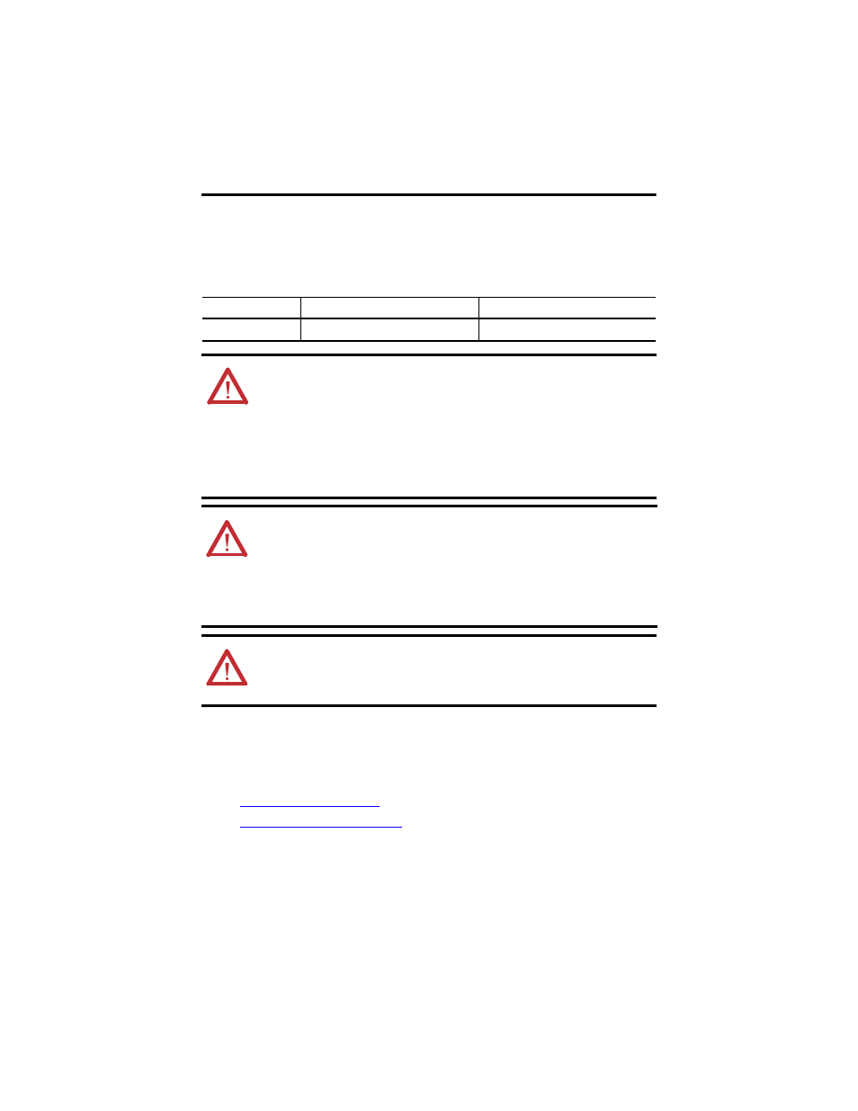
Panel Cutout Dimensions
You can print the panel cutout template that comes at the end of this installation instructions.
Panel cutout dimensions are provided in the next table.
Mount the Module
There are two ways to mount the Micro800 Remote LCD, as described in the following sections:
•
•
Mount the Module on a DIN Rail
Catalog Number
Height, Approx., mm (inches)
Width, Approx., mm (inches)
2080-REMLCD
88.5 ± 0.5 (3.48 ± 0.02)
121.5 ± 0.5 (4.78 ± 0.02)
ATTENTION: Disconnect all electrical power from the panel before
making the panel cutout.
•
Make sure the area around the panel cutout is clear.
•
Take precautions so metal cuttings do not enter any components
already installed in the panel.
•
Failure to follow these instructions may result in personal injury or
damage to panel components.
WARNING: If you connect or disconnect the RS232 cable with power
applied to this module or the RS232 device on the other end of the
cable, an electrical arc can occur. This could cause an explosion in
hazardous location installations.
Be sure that power is removed or the area is nonhazardous before
proceeding.
WARNING: When used in a Class I, Division 2, hazardous location, this
equipment must be mounted in a suitable enclosure with proper wiring
method that complies with the governing electrical codes.