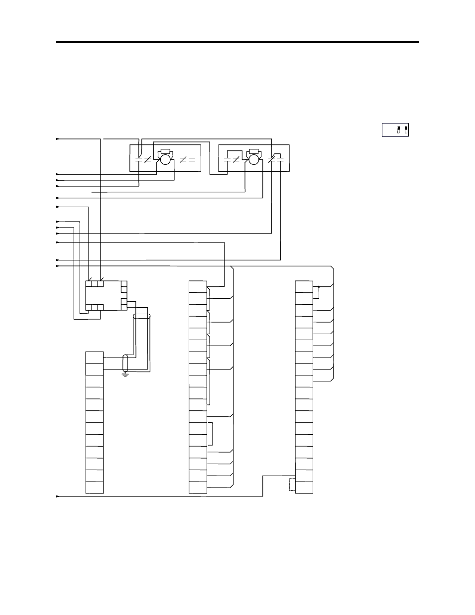
Figure 4.3 – typical schematic (sheet 3 of 3), Setup and commissioning 4-11, Sw1 2 1 – Rockwell Automation 1901 SyncPro User Manual
Page 37
Setup and Commissioning
4-11
1901-UM020C-EN-P – June 2013
Figure 4.3 – Typical Schematic (Sheet 3 of 3)
BLK
C
3
26
27
28
29
30
32
31
6
8
33
34
35
2
4
36
37
5
6
1
7
FCR
SS
9
5
ESR
SS
12
1
31
5
6
4
3
1
2
7
8
20
12
1
OUT 0
VAC 0
VAC 1
OUT 1
VAC 2
OUT 2
VAC 3
OUT 3
VAC 4
OUT 4
VAC 5
OUT 5
VAC 6
OUT 6
VAC 7
OUT 7
NOT
USED
NOT
USED
USED
NOT
USED
NOT
IN0+
IN0-
ANLCOM
IN1+
IN1-
ANLCOM
OUT 0
ANLCOM
ANLCOM
OUT 1
AC COM
AC COM
IN 15
IN 14
IN 13
IN 12
IN 11
IN 10
IN 9
IN 8
IN 7
IN 6
IN 5
IN 4
IN 3
IN 2
IN 0
IN 1
31
1
20
C3A
C3B
10
9
6
7
5
1
10
3
5
SLOT 4
120 VAC INPUT
1746-IA16
SLOT 3
120 VAC RELAY OUTPUT
1746-OX8
PHASE ANGLE
TRANSDUCER
SLOT 2
INPUT/OUTPUT MODULE
1746-NI041
FCR RELAY
TRIP (NOT FAULTED)
OPTIONAL SCP TRIP
PILOT LIGHT
OPTIONAL MOTOR
PULLOUT TRIP
PILOT LIGHT
OPTIONAL INCOMPLETE
SEQUENCE TRIP
PILOT LIGHT
RUN
AUTOLOAD
COMMONS
CONNECTED
INTERNALLY
MAIN CONTACTOR
M
FEEDBACK CONTACTOR
NOT STOP
START
RESET
FIELD VOLTAGE RELAY
M
FIELD CONTACTOR
M
FEEDBACK CONTACTOR
SYNCHRONIZATION ENABLE INPUT
MN
(TRANSITION COMPLETE)
FIELD LOSS RELAY (CURRENT)
MN
EQUIPMENT SHUTDOWN RELAY INPUT
(RESET PERMITTED)
M
Customer supplied equipment.
N
FLR and TC are optional customer supplied inputs which
are jumpered to terminal blocks, if not used.
O
Contact rating is 60 amp Make, 10 amp Break (inductive)
– 10 amp continuous at 120 V AC (A600).
P
Refer to instruction manual for tap selection guidelines on
R
F
1 and R
F
2 resistors.
Q
Analog card switch settings are:
R
Customer to take ground wire to ground bus (earth ground).
S
Ground at bottom left hand mounting screw for rack or
grounding bar.
T
Line 1 to Line 2 voltage reference and Line 3 current reference
must be maintained for proper operation of the phase angle
transducer.
U
Wiring supplied on enclosed assembly only (1901-AADC10)
for the open frame units. The customer must supply these
wires in addition to mounting the illuminated push button.
DTAM, STAM cable (1747-C10) and illuminated push button
are supplied loose on open frame assemblies. (1901-ANDC10)
SW1
2 1
ON
OFF