Grounding – Rockwell Automation 1901 SyncPro User Manual
Page 21
Installation
3-3
1901-UM020C-EN-P – June 2013
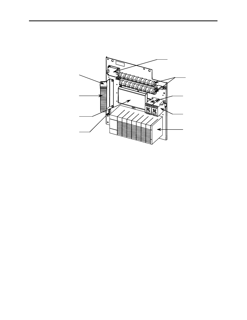
Open Frame (cont.)
Fusible Terminal Blocks
Terminal Blocks
Phase Angle Transducer
(DIN Rail Mounted)
Ground Bar
ESR Relay
(DIN Rail Mounted)
Bulletin 1746
7-slot Card Rack
with P1 Power Supply
FCR Relay
(DIN Rail Mounted)
Analog/Digital
Pulse Converter Board
Conditioning
Resistors, RF
Fusible Terminal Blocks
Terminal Blocks
Phase Angle Transducer
(DIN Rail Mounted)
Ground Bar
ESR Relay
(DIN Rail Mounted)
Bulletin 1746
7-slot Card Rack
with P1 Power Supply
FCR Relay
(DIN Rail Mounted)
Analog/Digital
Pulse Converter Board
Conditioning
Resistors, RF
Figure 3.3 – Component Layout
Integral
The SyncPro is also available as a component of a Rockwell
Automation/Allen-Bradley synchronous motor starter (Bulletin
1912B) incorporating the components shown in Figure 3.3.
Although the layout in the starter is different, control and
functionality remain the same.
Grounding
The grounding required by the SyncPro panel has been brought to
a common grounding bar mounted on the panel. It is important
that once the unit is installed, that this grounding bar is wired to
the starter ground bus. It is important that a proper ground is made
as the SyncPro has a number of low voltage signals which, if not
properly grounded, may be vulnerable to noise causing erratic
operation.
NOTE: For grounding requirements of the DTAM, refer to
Publication 1747-NC013.