Schematics and connector pinouts for cables – Rockwell Automation 2090-CPWM7DF-xxAFxx Continuous Flex Power Cables with DIN SpeedTec Connector Installation Instruc User Manual
Page 6
6 Continuous Flexible Power Cables Installation Instructions
Publication 2090-IN025A-EN-P — October 2009
Schematics and Connector Pinouts for Cables
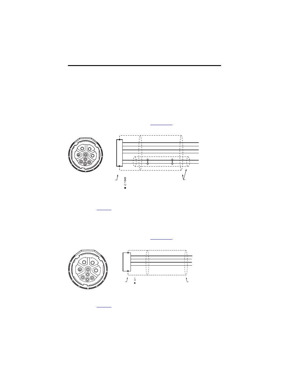
Schematics show wire colors and connector pinouts necessary to connect the cable
to a servo system.
2090-CPBM7DF-xxAFxx
This cable is available in several wire gauges and lengths. Refer to the Kinetix
Motion Control Selection Guide, publication
his information and
additional specifications.
1
Wire gauge and connector keying varies based on motor and power requirements. Refer to Kinetix Motion Control Selection
Guide, publicati
, for additional information.
2090-CPWM7DF-xxAFxx
This cable is available in several wire gauges and lengths. Refer to the Kinetix
Motion Control Selection Guide, publication
his information and
additional specifications.
1
Wire gauge and connector keying varies based on motor and power requirements. Refer to Kinetix Motion Control Selection
Guide, publicati
, for additional information.
U
V
W
GND
MBRK+
MBRK-
1
1
1
1
A
B
C
D
F
G
C
C
B
A
E
F
G
H
L
Brown
Black
Blue
Green/Yellow
18 AWG White
18 AWG Black
Shield
Twisted Wire Pair
360° shield-to-ground
connections required.
To
Motor
Connector Backshell
Shielded 360°
Shield
Wire Connection
To
Drive
1
1
1
1
Brown
Black
Blue
Green/Yellow
Shield
A
B
C
D
U
V
W
GND
C
C
B
A
E
F
G
H
L
360°
shield-to-ground
connection required.
To
Motor
Shield
Wire Connection
To
Drive
Connector
Backshell
Shielded 360°