Install cables – Rockwell Automation 2090-CPWM7DF-xxAFxx Continuous Flex Power Cables with DIN SpeedTec Connector Installation Instruc User Manual
Page 4
4 Continuous Flexible Power Cables Installation Instructions
Publication 2090-IN025A-EN-P — October 2009
Install Cables
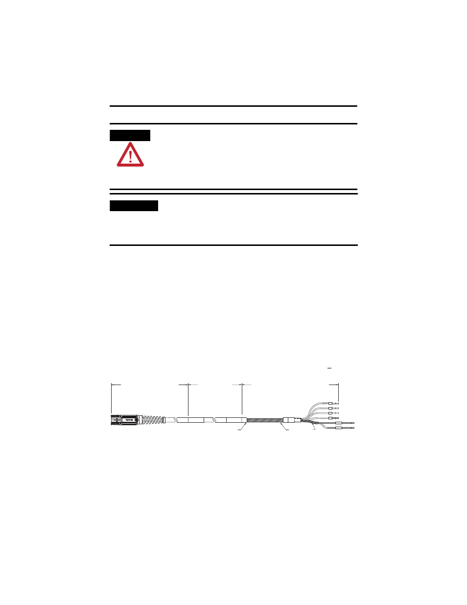
Follow these steps when installing a cable.
1. Identify the recommended installation areas and the correct offset from
features before beginning any cable bend. Features include these areas on
the cable:
• Connectors
• Transitions from exposed wire to insulation (for example, flying leads)
• Exposed cable ground shields
The offset from these features should be greater than or equal to (>1x) the
cable diameter.
2. Keep cable bends within the specified bend radius. Continuous flexible
cables have an operational bend radius of twelve times (12x) the cable
diameter.
ATTENTION
The examples in this publication show all the available connections, some of which
may not be appropriate for your specific installation. Refer to your drive installation or
user manual for recommended wire trim lengths, and wiring examples appropriate to
your drive and motor application.
Do not connect unused wires. Unused wires may be trimmed and finished as necessary
to prevent accidental contact with other wires or wire shields, or with a ground
connection.
IMPORTANT
Continuos flexible cables with SpeedTec connectors are incompatible with some
MP-Series motors.
Only install cables with a threaded connector on these motors: MPL-A15x0, MPL-A2x0,
MPL-B15x0, MPL-B2x0, MPS-A330, MPS-A4540, MPS-B330, MPS-B4540, and
MPS-B560.
U
Y
W
PE
WHITE
BLACK
MBRK+
MBRK-
Feature Offset
Minimum of 1x Cable Diameter
Flex Zone
2090-CPBM7DF-xxAFxx shown
Installation Area
300 mm (12 in.)
approx.
Installation Area
300 mm (12 in.)
approx.
Exposed
Shields