Figure 2.4 4 way ebu with follower drive – Rockwell Automation 4100-EF04_EF08 4 or 8 Way Encoder Buffer Unit Installation and Setup Manual User Manual
Page 21
Publication 4100-IN054B-EN-P - January 2001
Installation 2-5
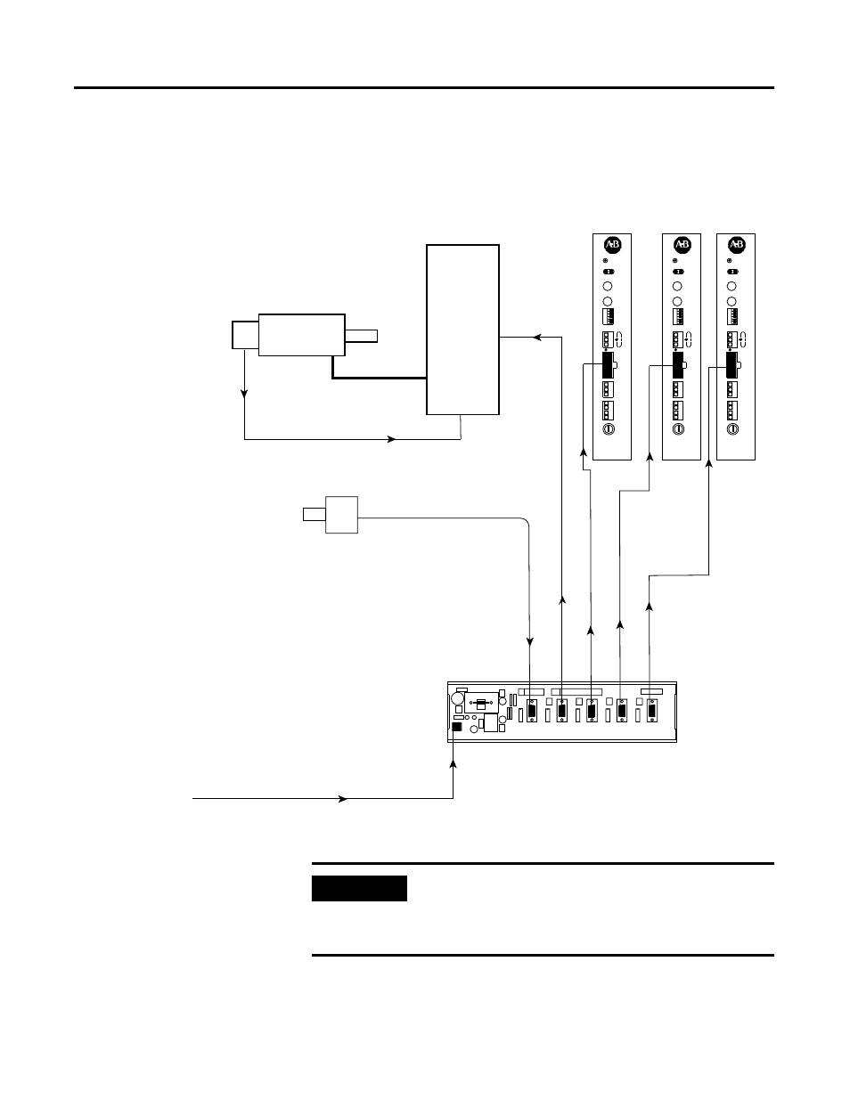
ALEC units are also shown connected to other follower outputs
demonstrating that a combination of ALEC modules and follower
drives is permissible.
Figure 2.4 4 Way EBU with Follower Drive
4 Channel Encoder Buffer
+12V +5V
HEALTHY
P1
P2
P3
P4
P5
P6
MASTER
FLWR-1
FLWR-2
FLWR-3
FLWR-4
LK-Volts ENC VOLTAGE
LK-DIR
ENCODER DIRECTION
LK-5V-F1
LK-5V-F2
LK-5V-F3
LK-5V-F4
FOLLOWER POWER LK-5V-FX
24V DC Power
System Control Encoder
4 Channel Encoder Buffer Unit
QUALITY
ALEC
Fuse
Common
24V DC
F
a
ult P
o
w
e
r
Rela
y Input
Registr
ation
Input
Incremental
Encoder Input
Encoder OK
AxisLink
1
2
AxisLink
Address
Mode
AL
CPU OK
Reset
12V/5V
Extd Node On/Off
Enc. Fault On/Off
Extd Length On/Off
Extd Term 1 On/Off
Extd Term 2 On/Off
12
3
4
5
6
QUALITY
ALEC
Fuse
Common
24V DC
F
ault P
o
w
e
r
Rela
y Input
Registr
ation
Input
Incremental
Encoder Input
Encoder OK
AxisLink
1
2
AxisLink
Address
Mode
AL
CPU OK
Reset
12V/5V
Extd Node On/Off
Enc. Fault On/Off
Extd Length On/Off
Extd Term 1 On/Off
Extd Term 2 On/Off
12
3
4
5
6
QUALITY
ALEC
Fuse
Common
24V DC
F
ault P
o
w
e
r
Rela
y Input
Registr
ation
Input
Incremental
Encoder Input
Encoder OK
AxisLink
1
2
AxisLink
Address
Mode
AL
CPU OK
Reset
12V/5V
Extd Node On/Off
Enc. Fault On/Off
Extd Length On/Off
Extd Term 1 On/Off
Extd Term 2 On/Off
12
3
4
5
6
ALEC 1
ALEC 2
ALEC 3
Motor
Follower
Encoder
Power
Follower
Encoder
Master
Encoder
FOLLOWER DRIVE
IMPORTANT
P3 is the only output to which the motor thermal
information and analog position reference are
brought out. Only this output should be used to
complete the encoder feedback loop.