Rockwell Automation 2100 CENTERLINE Motor Control Center (MCC) Units with Vertical Operating Handles User Manual
Page 9
Rockwell Automation Publication 2100-IN014F-EN-P - March 2014
9
CENTERLINE 2100 Motor Control Center (MCC) Units with Vertical Operating Handles
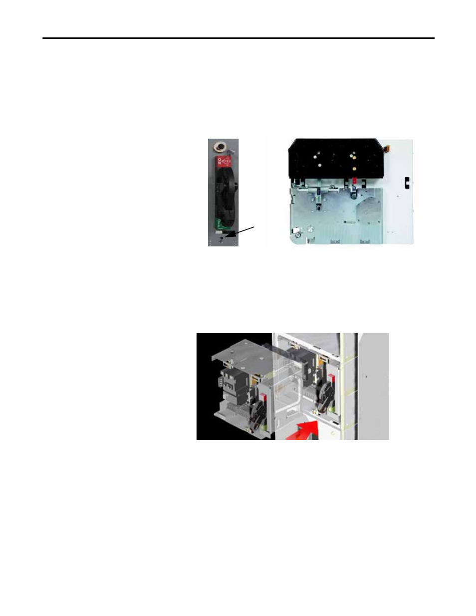
2. For SecureConnect units, make sure the breaker handle is in the OFF
position and that the power stabs are retracted.
a. If the stabs are not retracted, insert the 1/4 in. hex tool into the shaft
port.
b. Rotate the wrench counter-clockwise to make sure the stabs are
retracted and the stab shutters are closed.
3. Reposition your hands as necessary to properly support the unit while you
are installing the unit into the MCC.
4. For SecureConnect units, place the unit on the unit support pan and slide
it into the section until it is flush with the front of the structure.
5. For all other units, place the unit on the unit support pan and slide it into
the section until it is flush with the front of the structure and the power
stabs are connected to the vertical bus.
Shaft Port
TIP
For the CENTERLINE 2100 MCC units with swing-out door latches, it is
necessary to rotate the movable portion of the latch bracket to a vertical
orientation to avoid interference when installing the unit.
TIP
For the CENTERLINE 2100 MCC units with arc-resistant door latches, you may
need to tilt the top of the unit slightly to the rear to avoid interference with the
top arc latch bracket. If you do not have enough clearance, you will need to
loosen the latch bracket screw (approximately two turns) to install the unit.