Concluding steps – Rockwell Automation 2361 Feedback Board Replacement User Manual
Page 5
Feedback Board Replacement (for 1250, 1650, and 3000A 1395 DC Drives)
5
Publication 2361-5.10 - May 1998
8.
Verify the following:
•
Verify AC line voltage parameter 116 with an AC volt-
meter.
•
Verify DC field current parameter 118 with a DC amme-
ter in the field circuit.
•
Verify DC armature voltage parameter 105 with a DC
voltmeter
Note: The start-up chapter of publication 1395-5.40 provides
more detail for verifying parameters.
Concluding Steps
After installing the feedback board, replace all Lexan shielding and
secure the disconnect bay door. Dispose of old parts according to
your company procedures and local codes.
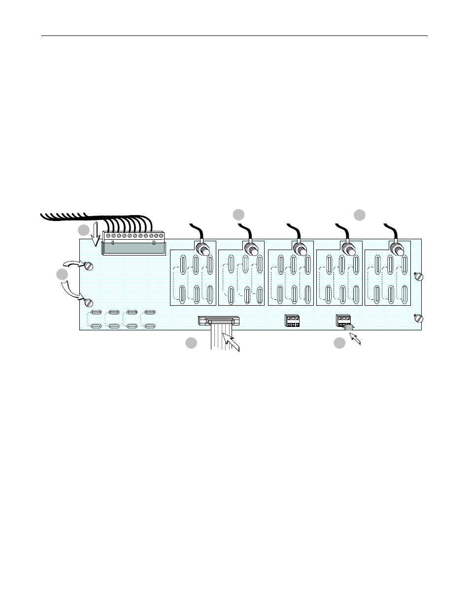
5
576VAC
TO
690VAC
301VAC
TO
575VAC
150 VAC
TO
300 VAC
150 VAC
TO
300 VAC
301VAC
TO
575VAC
576VAC
TO
690VAC
150 VAC
TO
300 VAC
576VAC
TO
690VAC
150 VAC
TO
300 VAC
301VAC
TO
575VAC
576VAC
TO
690VAC
301VAC
TO
575VAC
150 VAC
TO
300 VAC
TB2
TB3
FEEDBACK BURDEN RESISTOR
FEEDBACK BURDEN RE ARMATURE
A
B
C
VA+
TB1
(1)
(2)
(3)
(4)
301VAC
TO
575VAC
576VAC
TO
690VAC
VA-
1
7
4
3
6
(Not Used)