Preliminary steps, Removing the feedback board – Rockwell Automation 2361 Feedback Board Replacement User Manual
Page 3
Feedback Board Replacement (for 1250, 1650, and 3000A 1395 DC Drives)
3
Publication 2361-5.10 - May 1998
Preliminary Steps
Before replacing the feedback board, shut off the drive power, wait
five minutes for the voltage to discharge, open the disconnect bay
door, and remove the Lexan™ shielding.
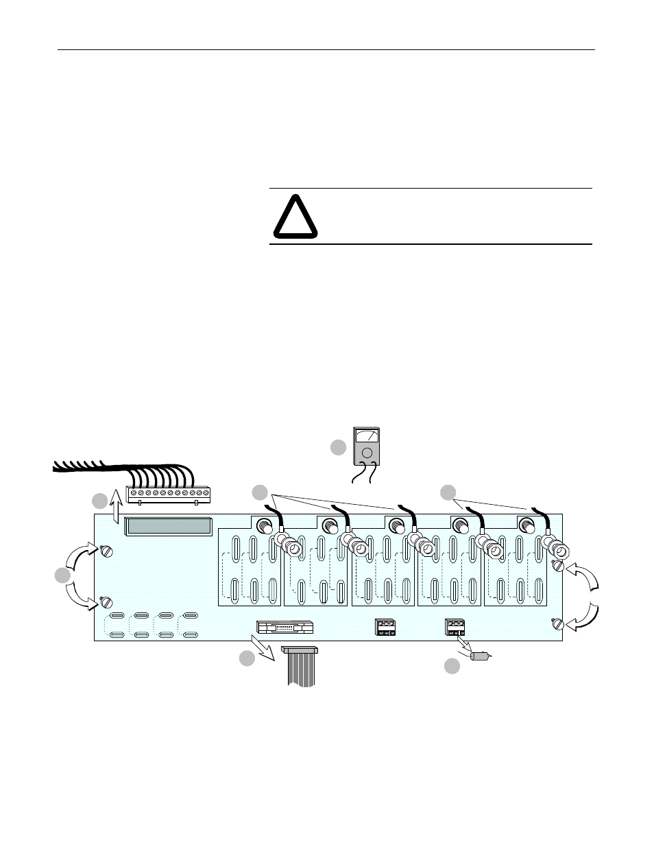
Removing the Feedback Board
1.
Using a voltmeter, verify that no AC voltage exists between
terminals A and B, B and C, and A and C. Also verify that there
is no DC voltage between terminals VA+ and VA-.
2.
Disconnect the AC input leads A (J1), B (J2), and C (J3).
3.
Disconnect the armature voltage feedback leads VA+ (J4) and
VA- (J5).
4.
Remove the ribbon cable at J40.
5.
Remove the connector at TB1.
6.
Loosen the four set screws to remove the feedback board.
7.
Remove the armature feedback burden resistor in TB3 (check if
the resistor is damaged).
!
ATTENTION: If there is any voltage present, remove
the source of the voltage and check the terminals again
before proceeding to the next step.
4
576VAC
TO
690VAC
301VAC
TO
575VAC
150 VAC
TO
300 VAC
150 VAC
TO
300 VAC
301VAC
TO
575VAC
576VAC
TO
690VAC
150 VAC
TO
300 VAC
J40
576VAC
TO
690VAC
150 VAC
TO
300 VAC
301VAC
TO
575VAC
576VAC
TO
690VAC
301VAC
TO
575VAC
150 VAC
TO
300 VAC
TB2
TB3
FEEDBACK BURDEN RESISTOR
FEEDBACK BURDEN R ISTOR ARMATURE
A
B
C
VA+
TB1
(1)
(2)
(3)
(4)
301VAC
TO
575VAC
576VAC
TO
690VAC
VA-
7
2
3
5
6
1