Module spacing, Din rail mounting – Rockwell Automation 2085-IF4_IF8_OF4 Micro800 4-channel and 8-channel Analog Voltage/current Input and Output Modules User Manual
Page 7
Micro800 4-channel and 8-channel Analog Voltage/current Input and Output Modules 7
Publication 2085-IN006A-EN-P - September 2012
Module Spacing
Maintain spacing from objects such as enclosure walls, wireways and adjacent equipment. Allow
50.8 mm (2 in.) of space on all sides for adequate ventilation, as shown.
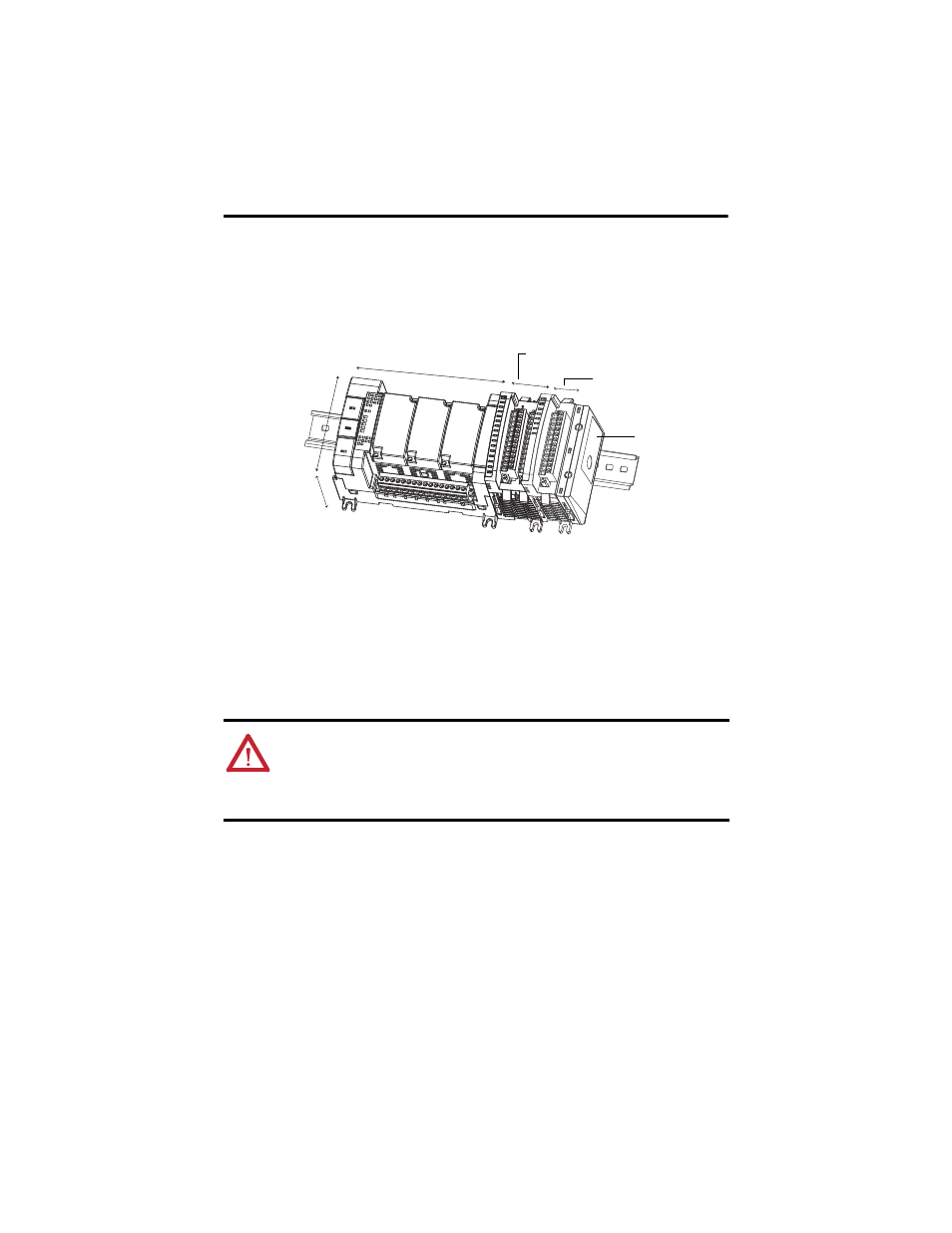
Mounting Dimensions and DIN Rail Mounting
DIN Rail Mounting
The module can be mounted using the following DIN rails: 35 x 7.5 mm x 1 mm
(EN 50 022 - 35 x 7.5)
.
Before mounting the module on a DIN rail, use a flat-blade screwdriver in the DIN rail latch and
pry it downwards until it is in the unlatched position.
1. Hook the top of the DIN rail mounting area of the module onto the DIN rail, and then
press the bottom until the module snaps onto the DIN rail.
2. Push the DIN rail latch back into the latched position.
Use DIN rail end anchors (Allen-Bradley part number 1492-EAJ35 or 1492-EAHJ35)
for vibration or shock environments.
To remove your module from the DIN rail, pry the DIN rail latch downwards until it is in the
unlatched position.
TIP
For environments with greater vibration and shock concerns, use the panel mounting
method, instead of DIN rail mounting.
ATTENTION: This product is grounded through the DIN rail to chassis ground. Use zinc plated
yellow-chromate steel DIN rail to assure proper grounding. The use of other DIN rail materials
(for example, aluminum or plastic) that can corrode, oxidize, or are poor conductors, can result
in improper or intermittent grounding. Secure DIN rail to mounting surface approximately every
200 mm (7.8 in.) and use end-anchors appropriately.
45306
Mounting dimensions do not include mounting feet or DIN rail latches.
90 mm
(3.54 in.)
150 mm (5.91 in.)
2085-IF4 or 2085-OF4
2085-IF8
Micro850 Controller
Bus terminator
28 mm (1.1 in.)
44.5 mm (1.75 in.)
87 mm (3.42 in.)