Rockwell Automation 2364P Overhead Bus for Bulletin 2300 MCCs User Manual
Page 4
Publication 2364P-5.10 - December 1999
4
Note: Verify that there is sufficient working space above and around
the MCCs. If not, install the bus tabs and splices before placing the bus
assemblies on the MCC sections.
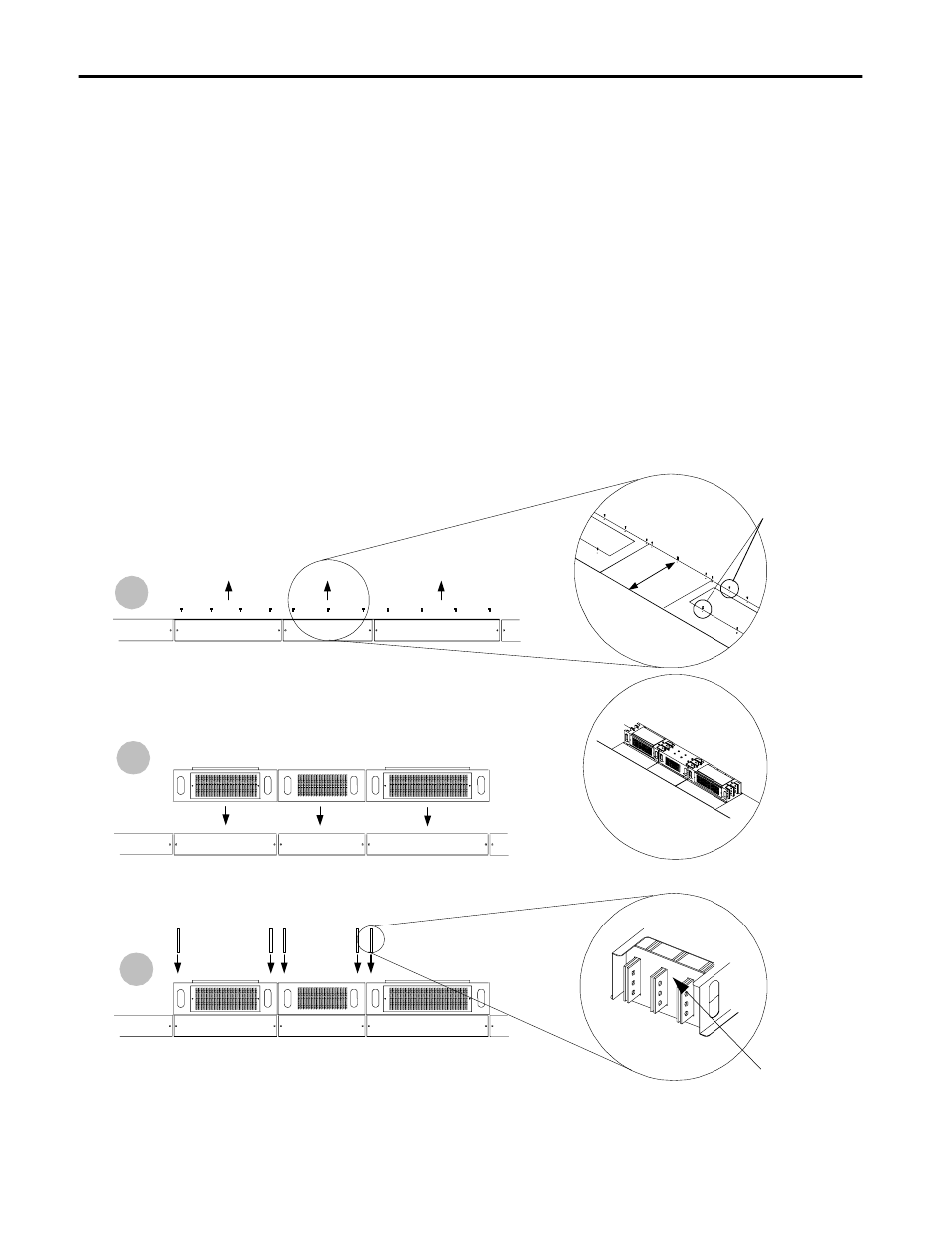
1.
Remove the bus assembly mounting screws from the MCCs as shown
in Figure 3, Step 1. These screws will be used in step 7 to mount the
bus assemblies to the MCCs.
2.
With the Certified Cabinet Outline Drawing as a guide, place all of the
assemblies onto the MCC sections (as shown in Figure 3, Step 2).
Align the mounting holes in the rear of the MCC. Do not fasten the
assemblies to the MCCs at this time.
3.
Place an insulator over each set of 3-phase busbars to be spliced, includ-
ing the busbars to be spliced to the feeder (see Figure 3, Step 3).
Figure 3
Installation Example–Steps 1 - 3
2
3
1
#10 Taptite
Screws (typ.)
Insulator
Step
Step
Step
20 in
(51mm)