Indicators, Indicators -4 – Rockwell Automation 2706-PRIO_PDH485_PDHP_PDNET_PCNET_PENET_PENET1 InView Communication Module User Manual User Manual
Page 106
Publication 2706-UM017C-EN-P - March 2006
5-4 InView Communication Module Troubleshooting
Indicators
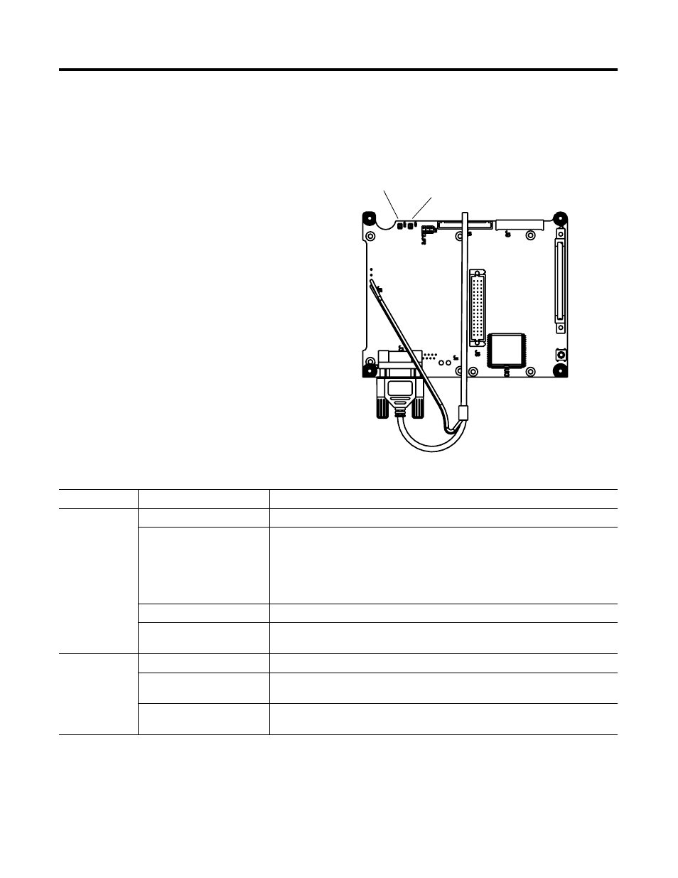
On InView communication modules, use the COMM and Fault LED
indicators to isolate operating problems. The illustration below shows
the location of these indicators.
Communication Module Indicators
Fault LED
(LED 1)
COMM LED
(LED 2)
DF1, DH-485, DH+ LED Indications
LED
This Pattern:
Indicates:
Comm
(1)
Solid Fill
Normal operating state (no communication faults).
No Fill
Fault detected.
• Make sure controller is run mode
• Verify communication rate settings of terminal and controller
• Verify proper InView communication module board to controller connections
Flashing
When power is first applied (momentarily).
Blinking
No communications established. For DF1 terminals, the Comm indicator flashes until
an application is loaded.
Fault
No Fill
Normal operating state
Solid
Fault detected. Cycle power to the InView communication module board. If the fault
still exists, the terminal requires servicing.
Blinking
Hardware is functioning but no application is loaded or the current application is
corrupt. Reload the application into the InView communication module board.
(1)
Comm LED stays on until powerup self-tests are complete.