Rockwell Automation 1753-IB16XOB8 GuardPLC 16-Digital Inputs and 8-Digital Outputs Installation Instructions User Manual
Page 11
GuardPLC 16-Digital Inputs and 8-Digital Outputs Module 11
Publication 1753-IN011A-EN-P - October 2005
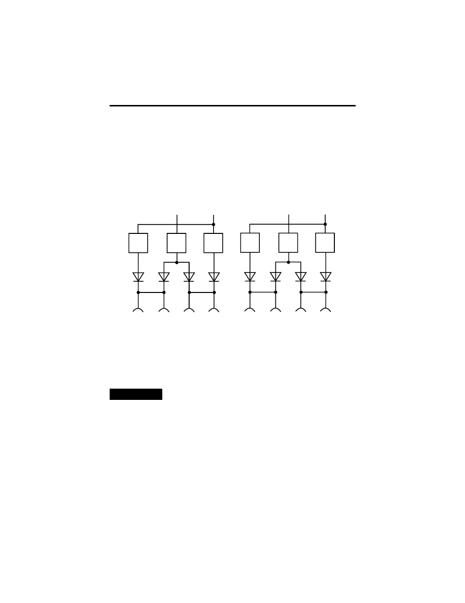
The sensor supplies, LS+, supply a default current of 40 mA that is buffered for 20
ms in case of a power failure. If a higher current is needed, two unbuffered
supplies of 1 A can be switched on using the DI Supply [xx] system signal in the
application program. This supply feeds the neighboring input channel group. The
status of this supply is read and the supply is switched off if an overcurrent
condition occurs. This supply is protected by a current limiting device. The
following illustration shows two digital input supplies for four different input
groups.
Follow the closed-circuit principle for external wiring when connecting sensors. To
create a safe state in the event of a fault, the input signals revert to the de-energized
state (0). Although the external line is not monitored, a wire break is interpreted as
a safe 0-signal. Unused inputs must not be terminated.
TIP
For more information on input wiring, see the GuardPLC
System User Manual, publication number 1753-UM001.
L+ not buffered
L+ buffered
LS+
33
LS+
34
LS+
43
LS+
44
Current
limiting
40 mA
Current
limiting
40 mA
Current
limiting
1 A
L+ not buffered
L+ buffered
LS+
53
LS+
54
LS+
63
LS+
64
Current
limiting
40 mA
Current
limiting
40 mA
Current
limiting
1 A