Determining power requirements, Controlnet connectors, Network address switch assemblies – Rockwell Automation 1747-ACNR15 ControlNet Adapter Module Installation Instructions User Manual
Page 6
6 ControlNet Adapter Module
Publication 1747-IN017C-EN-P - May 2001
ControlNet Connectors
Cable connection to the module is through standard BNC connectors on the front
of the module, as shown below.
.
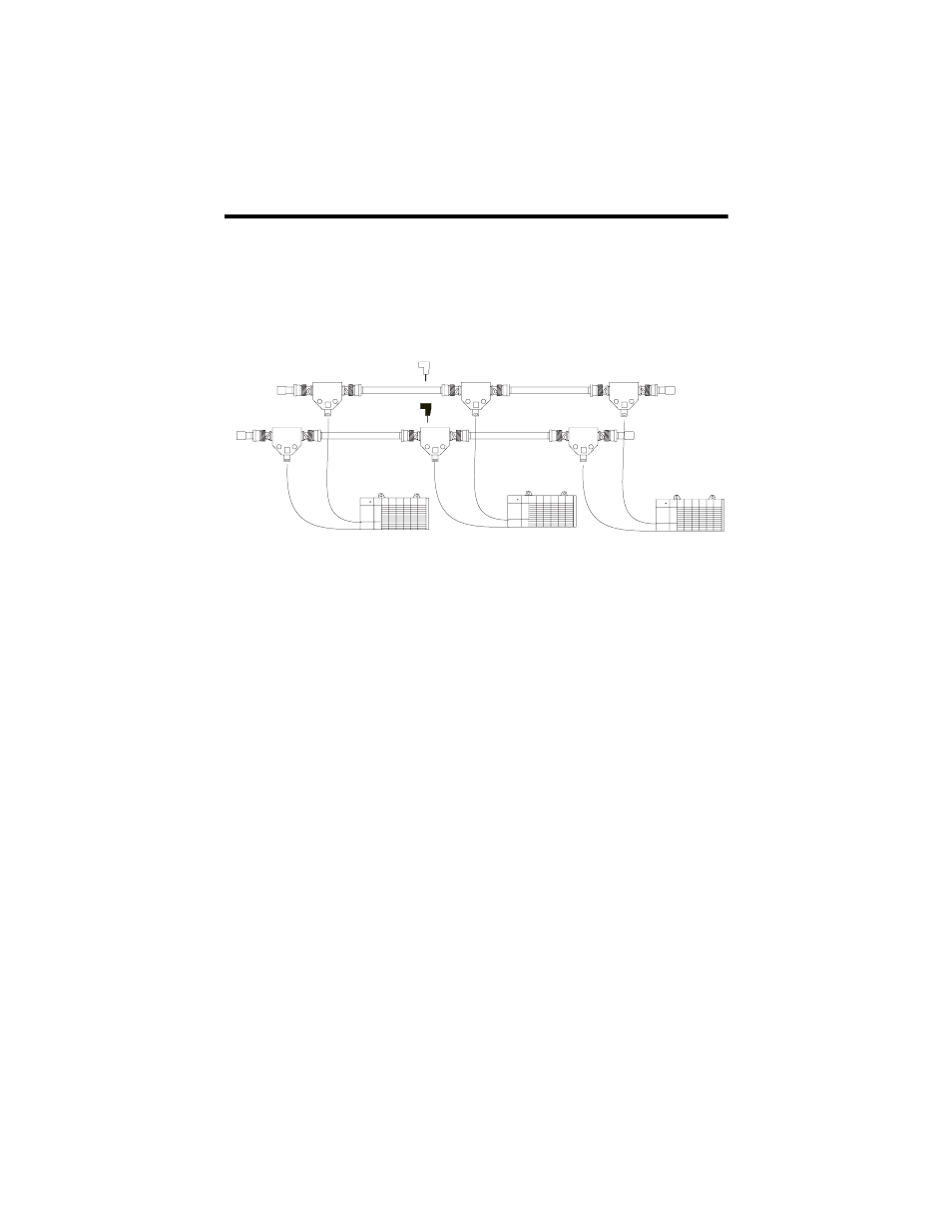
1. End device supporting redundant cabling is a 1747-ACNR15.
Refer to the ControlNet Cable System Planning and Installation User Manual,
Publication 1786-6.2.1 for more information.
Network Address Switch Assemblies
You must set two switch assemblies to configure your adapter module with its
unique network address. You access these switches through the top of the module.
The following figure shows the location of the switches. These switches are read on
power-up to establish the network address of the module. Network address switch
settings are described on page 7.
Determining Power Requirements
The ControlNet adapter module requires a maximum backplane current of 900mA
at 5VDC. Remember to add this amount to other current requirements for your I/O
chassis.
B
A
Example of a Redundant System
trunkline A =
trunkline B =
Terminator
Terminator
SLC 5/02 or later
with 1747-SCNR
end device
1