Make safety-related communication connections – Rockwell Automation 1753-OW8 GuardPLC 8-Relay Output Module Installation Instructions User Manual
Page 8
8 GuardPLC Relay Output Module
Rockwell Automation Publication 1753-IN012C-EN-P - June 2010
If the 1753-OW8 module faults, all eight outputs are switched off. This is indicated by the Fault
status indicator.
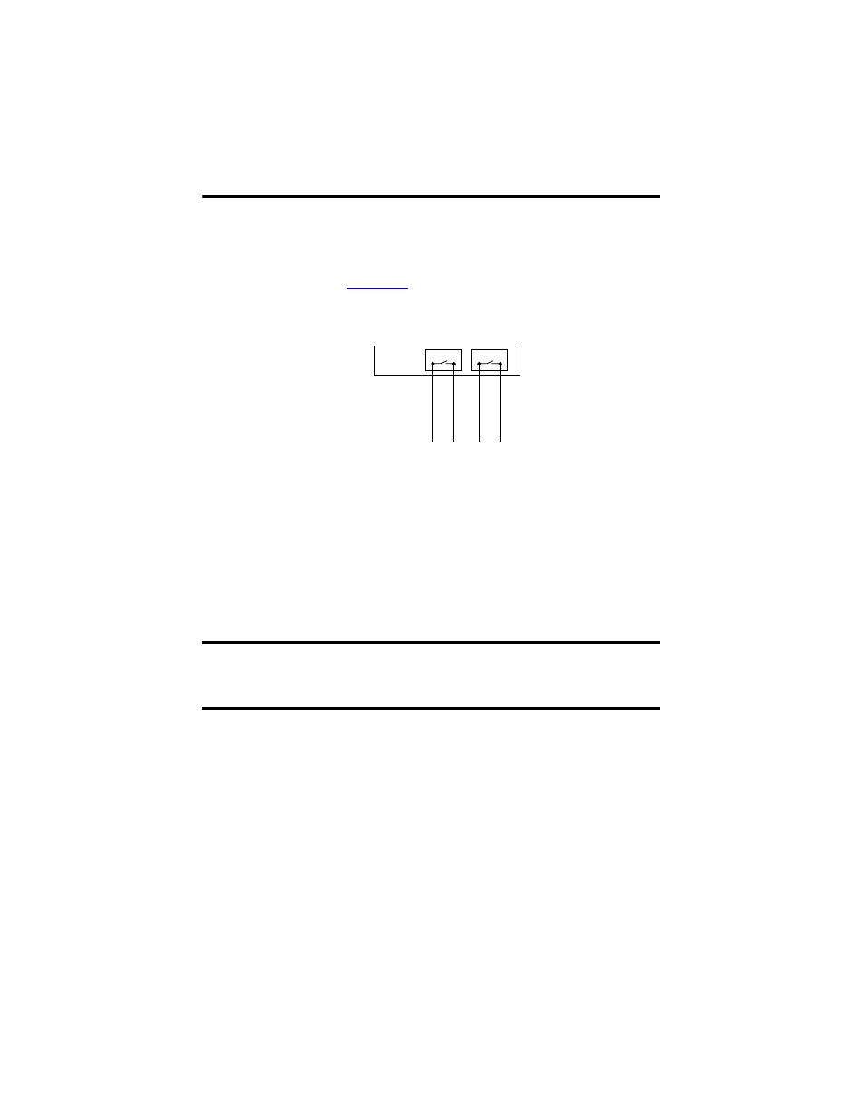
Output Connection Example
Make Safety-related Communication Connections
The module has two 10/100BaseT, RJ45 connectors on the bottom side of the unit to provide
communication to the GuardPLC controller via GuardPLC Ethernet protocol. Because this is
an Ethernet switch, you can daisy-chain connections from the GuardPLC controller to other
distributed I/O modules. The switch is auto-detect. Use either crossover or straight-through
shielded Ethernet cabling.
Star or line configurations are available. Make sure that a network loop is not generated. Data
packets must be able to reach a node only via a single path. Ring topology is not supported.
TIP
For more information on output wiring, see the GuardPLC System User Manual,
publication
IMPORTANT
In the event of a communication fault between the GuardPLC controller and
the 1753-OW8 module, the relay outputs will be set to their initial value. The
initial value is configured during signal creation in the hardware management
window of RSLogix Guard PLUS! software.
TIP
The media access control (MAC) address of the module is printed on the label
positioned over both lower RJ45 connections.
DO 1
DO 2
1
2
3
4