Mount the module, Ip address label – Rockwell Automation 1753-OW8 GuardPLC 8-Relay Output Module Installation Instructions User Manual
Page 5
GuardPLC Relay Output Module 5
Rockwell Automation Publication 1753-IN012C-EN-P - June 2010
Mount the Module
The terminal connections meet the protection requirements according to IP20. For higher
requirements, the 1753-OW8 must be mounted in an enclosure. The clearance and creepage
distances are designed for overvoltage category 2 up to 300 V according to IEC 61131-2.
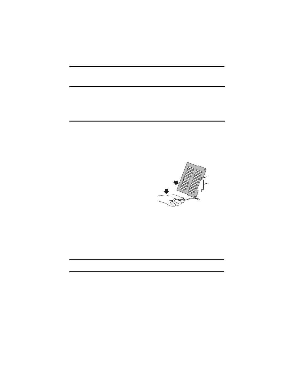
The module cannot be panel-mounted. Mount the module to a DIN rail by following these
steps.
1. Hook the top slot over the DIN rail.
2. Insert a flathead screwdriver into the gap
between the housing and the latch and pull
the latch downward.
3. Hold the latch down as you push the housing
back onto the DIN rail.
4. Release the latch to lock the device onto the
rail.
IP Address Label
Use the transparent label shipped with the module to note the IP Address and System ID (SRS).
IMPORTANT
For effective cooling, mount the module following these guidelines.
•
Mount the module horizontally.
•
Provide a gap of at least 100 mm (3.94 in.) above and below the module.
•
Select a location where air flows freely or use an additional fan.
•
Do not mount the module over a heating device.
TIP
To remove the module from the DIN rail, insert a flathead screwdriver into the
gap between the housing and the latch and pull the latch downward as you lift
the module off of the rail.
IMPORTANT
If you attach the label to the module, make sure you do not cover any of the
ventilation slots.
DIN Rail
(1) Top Slot
Latch
(3)
(2)