How the block i/o fits in a plc system – Rockwell Automation 1791-I0VX BLOCK I/O User Manual
Page 9
Introducing Block I/O
Chapter 1
1-3
Switch Assemblies - Two DIP switches are provided for setting the I/O
configuration and rack address.
The configuration switch lets you select baud rate, last state, processor
restart lockout, last rack and I/O group.
The rack address switch lets you select the system rack address for the
block.
A third switch is provided for selection of the termination resistor.
Status Indicators - Indicators are provided for power, active,
communication and fuse blown indications. An LED array provides
input/output status.
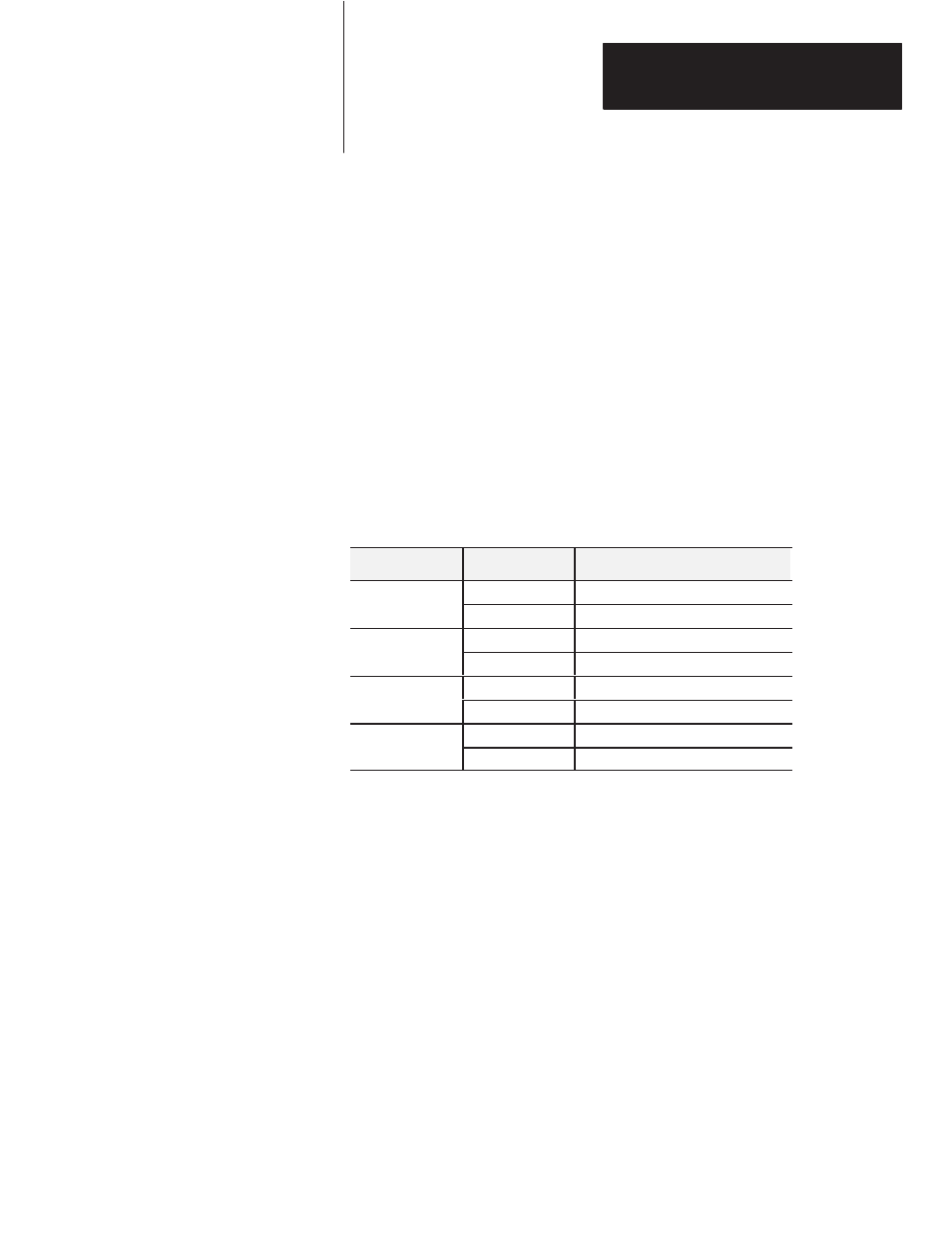
Status Indicators - Bi-color LED indicators provide power, active,
communication and fuse blown indications. An LED array provides
input/output status.
Indicator
Indication
P
On (green)
Customer voltage is present
Power (green/wht)
Off (wht)
No customer voltage (less than 2V)
A v
On (green)
CPU operating correctly
Active (green/red)
Off (red)
CPU not running
On (green)
Communication correctly established
Comm (green/wht)
Off (wht)
Communication not established
F
On (red)
One of the 4 output fuses is open
Fuse (red/wht)
Off (wht)
All fuses are intact
The I/O status array is an 8 by 8 array of 64 LEDs capable of displaying
the status of 32 inputs and 32 outputs at any one time. Pushbuttons are
provided to toggle the display between the lower 32 bits and the upper
32 bits.
Block I/O is a complete I/O interface that includes the functionality of the
I/O rack, adapter, power supply, and I/O modules in a single unit. Simply
connect sensors and actuators to the module and use the remote I/O cable
to connect the block I/O to your programmable controller (Figure 1.6).
The 1791-IOBX block uses sinking inputs and sourcing outputs.
How the Block I/O Fits in a
PLC System