Replacing a fuse – Rockwell Automation 1791-I0VX BLOCK I/O User Manual
Page 45
Troubleshooting
Chapter 4
4-3
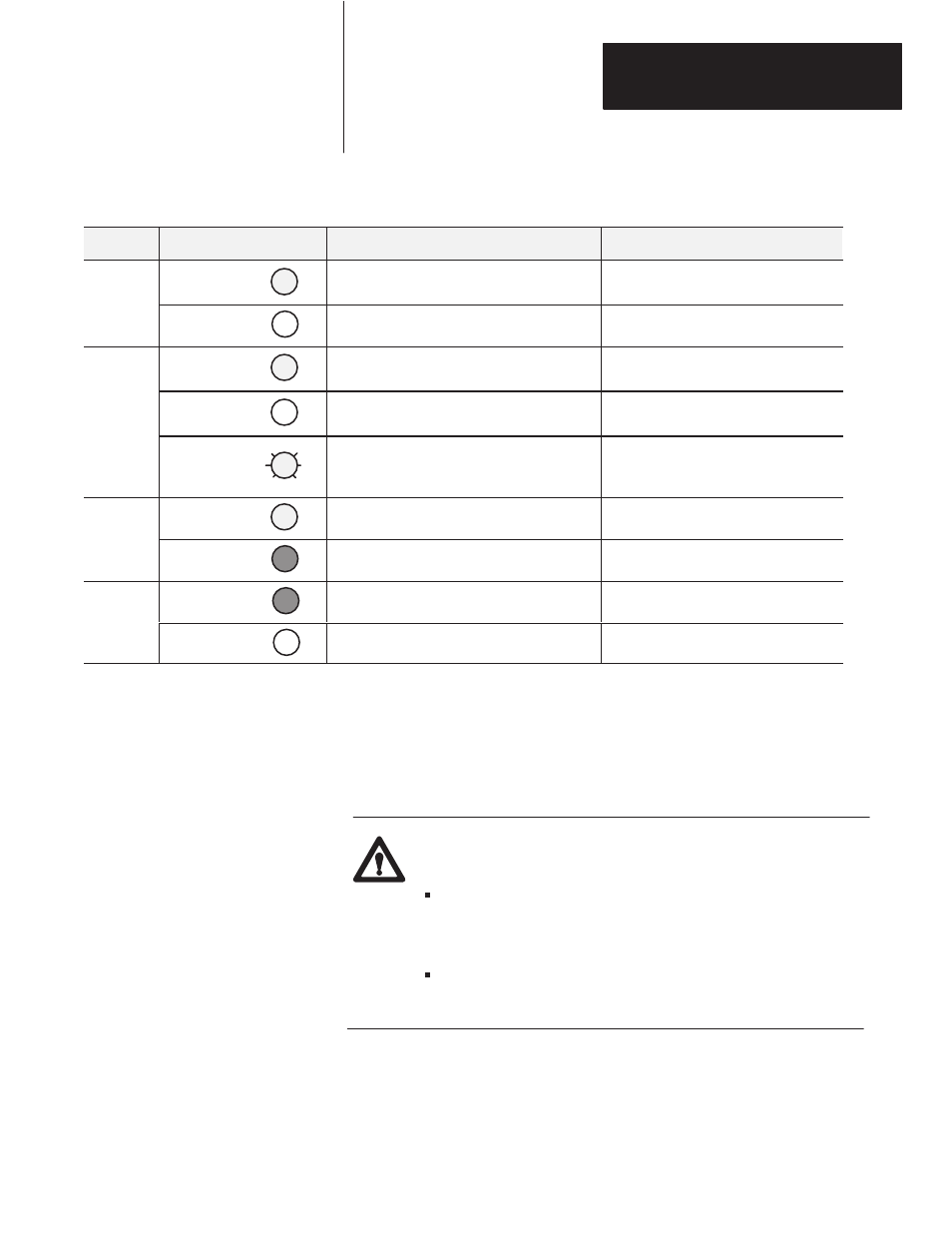
Table 4.A
Troubleshooting Chart
Indication
Probable Cause
Corrective Action
POWER
Green
I/O status on/off
Normal indication
None required
P WER
(green)
Off
No 24V dc power connected, or hardware fault.
Check 24V dc power to block
Solid green
Normal indication - module is communicating with
the programmable controller
None required
COMM
(green)
Off
No communication with adapter, scanner etc.
Check that power LED is on. Make sure that
proper number of blocks are configured.
(green)
Flashing green
Reset command (or output disable bit for SLC) has
been issued by processor, scanner or adapter.
SLC or programmable controller not in run mode.
Check program. Correct as necessary.
Place in run mode.
ACTIVE
Green
Normal indication
None
ACTIVE
(green/red)
Red
Internal CPU fault
Return module for repair
FUSE
Red
One or more fuses are open
Replace blown fuse
FUSE
(red)
Off
Normal indication
None required
The block I/O module has one fuse for each group of outputs. To replace a
fuse, proceed as follows.
1.
Remove power to the block I/O module.
ATTENTION: Remove power to the block I/O module before
attempting to replace the fuse.
Failure to remove power from the block I/O module could
cause injury or equipment damage due to possible
unexpected operation.
Failure to remove power from the module could cause
module damage, degradation of performance or injury.
2.
Remove the 5 screws securing the cover to the block I/O module.
3.
Locate and remove the blown fuse.
Replacing a Fuse