Configuring your block i/o chapter 3 – Rockwell Automation 1791-I0VX BLOCK I/O User Manual
Page 31
Configuring Your Block I/O
Chapter 3
3-3
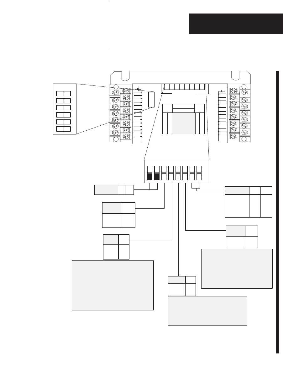
Figure 3.2
Configuration Switch Settings (PLC designations shown)
Latch
Reset
OFF
ON
3
0 to 3
4 to 7
6
57.6kbps
115.2kbps
230.4kbps
Unused
1 2
7 8
Disabled OFF
Enabled ON
4
NO OFF
YES ON
5
00
01
02
03
04
05
06
07
10
11
12
13
14
15
COM
RACK
ADDR
8 7 6 5 4 3 2 1
CONFIGURATION
SWITCHES
00
01
02
03
04
05
06
07
10
11
12
13
14
15
+VDC
L
(Top View of Switch)
Configuration Switch
Rack Address Switch
(Refer to Table 3.A)
ON
ON
8
7
6
5
4
3
2
1
1
3
42
5
6
10932-I
PLC-3
This switch must always be set to “OFF.”
PLC-2
OFF - When module does not contain the highest
numbered I/O group for the associated rack number.
ON - When module does contain the highest
numbered I/O group for the associated rack number.
PLC-5
This switch not used.
CAUTION: Set switch 3 to the ON position to
deenergize outputs wired to this module when
a fault is detected. If switch 3 is set to the
OFF position, outputs connected to this
module remain in their last state when a fault
occurs and machine motion may continue
after fault detection.
Last Rack Switch 5
Last State Switch 3
Processor Restart Lockout (PRL) Switch 4
-
When PRL is enabled (on), the programmable
controller cannot automatically start up the module’s
communications if the power has been cycled to
either the module or the programmable controller
OFF
ON
OFF
ON
OFF
ON
OFF
OFF
ON
ON
Not Used -
set to off
PRL
I/O
Group
L
AST
R
ACK
L
AST
S
TATE
B
AUD
R
ATE