Attention – Rockwell Automation 1747-OS302_OS401 SLC 5/03 and 5/04 Processors Firmware/Operating System Upgrade User Manual
Page 3
Publication 1747-IN007C-EN-P - October 2002
SLC 5/03™ and SLC 5/04™ Processors Firmware/Operating System Upgrade 3
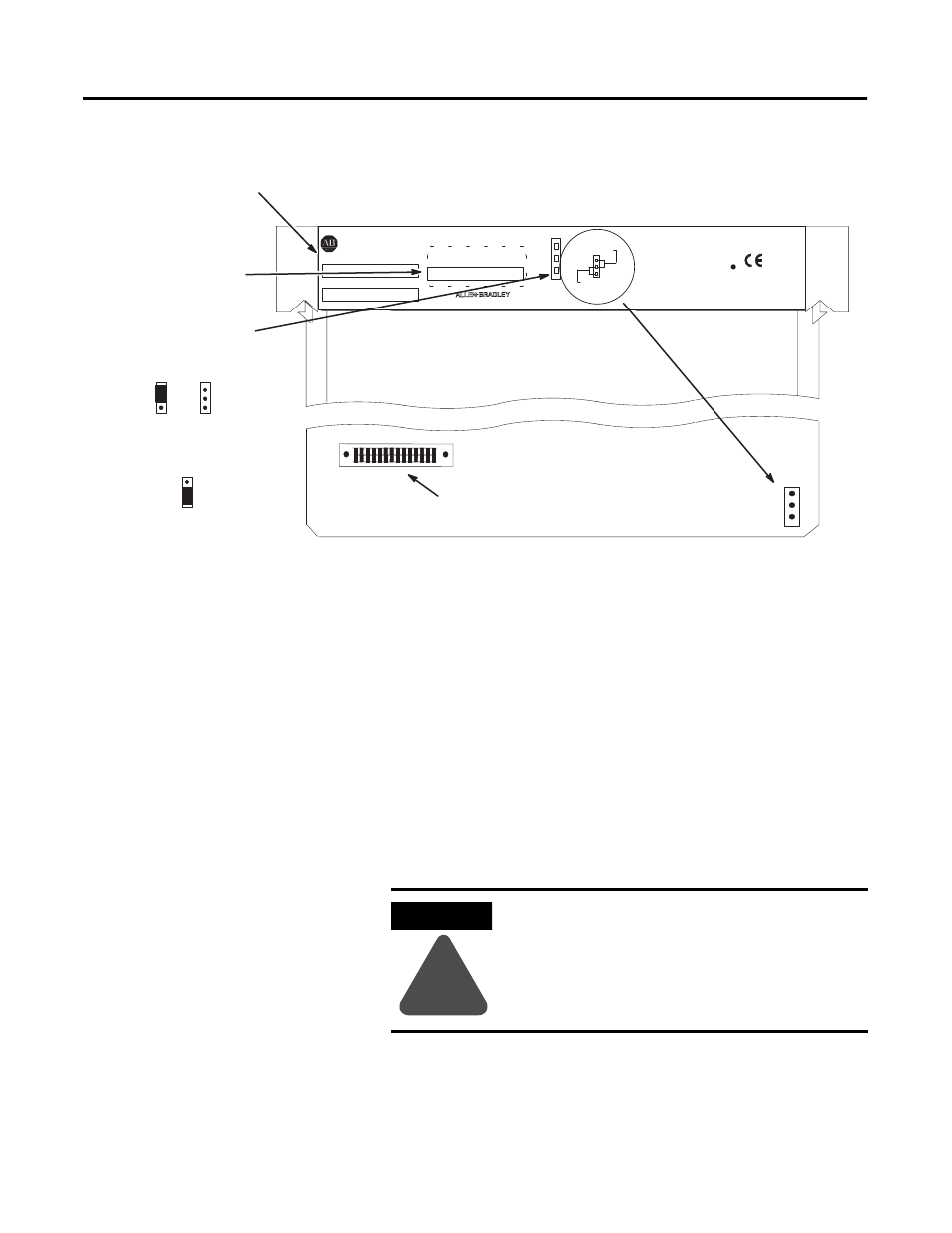
Figure 1 Component Placement Information
7. Firmly seat the processor back into the chassis.
8. Apply power to the chassis containing the processor while
watching the LED display. All the LEDs should turn on and then
turn off. The download process of the firmware takes up to 2.5
minutes. While the download is in progress, the RUN and FLT
LEDs remain off. The other four LEDs – RS232, DH485 (DH
+ on
the SLC 5/04), FORCE, and BATT – turn on and off in a walking
bit sequence. If the download is successful, these four LEDs
remain on together. If the FLT LED turns on and a combination
of LEDs flash on and off indicating an error condition, refer to
the troubleshooting information on page 4.
9. After completing the download, remove power from the chassis
containing the processor.
10. Remove the processor from the chassis.
11. Carefully remove the firmware upgrade pack and place it in the
anti-static packaging it was shipped in.
Jumper J4
Catalog and Serial
Number Label
The SLC 5/03 and SLC 5/04
processors are
protected from the
firmware download when jumper J4
is in this position:
The SLC 5/03 and SLC 5/04
processors accept the firmware
download when jumper J4 is in this
position:
Mother Board
Daughter Board
OR
SLC 500
CAT
SER
SERIAL NO.
PROC. REV.
UL
SA
PROCESSOR UNIT
MADE IN USA
LISTED IND. CONT. EQ.
FOR HAZ. LOC. A196
CLASS 1, GROUPS A, B, C AND D, DIV. 2
FAC
OPERATING TEMPERATURE CODE T3C
1
3
PROTECT
PROGRAM
J4
OS #
SER
FRN
OPERATING SYSTEM INFO
PLACE FRN UPGRADE LABEL HERE
WHITE
RED
+
-
BATTERY
CURRENT REQUIREMENTS: 1A @ 5 VDC
200mA @ 24 VDC
Place the firmware
upgrade label here.
Firmware
Upgrade/Memory
Module Socket
R
c
ATTENTION
!
Do not remove the processor from the SLC 500
chassis until all power is removed from the SLC
500 power supply.