Digital input terminals – Rockwell Automation 1753-L32BBBP-8A GuardPLC 1800 Controller User Manual
Page 8
8 GuardPLC 1800 Controllers
Rockwell Automation Publication 1753-IN002C-EN-P - June 2010
The safe state of an input is indicated by a 0 signal being passed to the user program logic. If the
test routines detect a fault in the digital inputs, a 0 signal is processed in the user program for the
defective channel. When a fault occurs, the inputs are switched off (0).
Follow the closed-circuit principle for external wiring when connecting sensors. To create a safe
state in the event of a fault, the input signals revert to the de-energized state (0). The FAULT
status indicator activates.
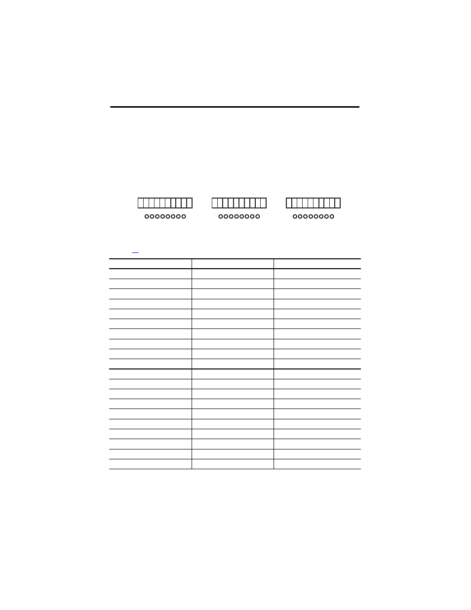
Digital Input Terminals
Terminals accommodate wires up to 1.5 mm
2
(16 AWG). See the terminal torque specifications
. Digital inputs are connected to these terminals.
Terminal Number
Designation
Function
11
LS+
Sensor supply for inputs 1…8
12
1
Digital input 1
13
2
Digital input 2
14
3
Digital input 3
15
4
Digital input 4
16
5
Digital input 5
17
6
Digital input 6
18
7
Digital input 7
19
8
Digital input 8
20
L-
Reference pole
21
LS+
Sensor supply for inputs 9…16
22
9
Digital input 9
23
10
Digital input 10
24
11
Digital input 11
25
12
Digital input 12
26
13
Digital input 13
27
14
Digital input 14
28
15
Digital input 15
29
16
Digital input 16
30
L-
Reference pole
20
17 18 19
11 12 13 14 15 16
11 12 13 14
1
LS+
L-
DI
2 3 4 5 6 7 8
15 16
17 18 19 20
30
27 28 29
21 22 23 24 25 26
21 22 23 24
1
LS+
L-
DI
2 3 4 5 6 7 8
25 26
27 28 29 30
40
37 38 39
31 32 33 34 35 36
31 32 33 34
1
LS+
L-
DI
2 3 4 5 6 7 8
35 36
37 38 39 40