Digital output terminals – Rockwell Automation 1753-L32BBBP-8A GuardPLC 1800 Controller User Manual
Page 13
GuardPLC 1800 Controllers 13
Rockwell Automation Publication 1753-IN002C-EN-P - June 2010
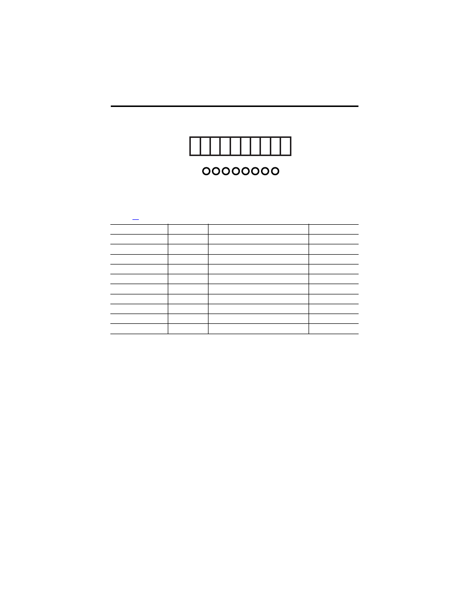
Digital Output Terminals
Terminals accommodate wires up to 1.5 mm
2
(16 AWG). See the terminal torque specifications
on page
. Digital outputs are connected to these terminals.
For connection of a load, the reference pole L- of the concerned channel group must be used
(2-pole connection). Although L- at terminals 1 and 6, 7 and 12 is connected internally to L- on
he power supply input, it is strictly recommended to use 1 and 6 for outputs 1…4 only and 7 and
12 for outputs 5…8 only. EMC testing was performed in this manner.
Terminal Number
Designation
Function
Current
1
L-
Reference pole
—
2
1
Digital output 1
0.5 A
3
2
Digital output 2
0.5 A
4
3
Digital output 3
0.5 A
5
4
Digital output 4 (for increased load)
2.0 A
6
5
Digital output 5
0.5 A
7
6
Digital output 6
0.5 A
8
7
Digital output 7
0.5 A
9
8
Digital output 8 (for increased load)
2.0 A
10
L-
Reference pole
—
1
2
3
4
5
6
1
2
3
4
1
L-
L-
DO
2
(2A)
(2A)
3
4
5
6
7
8
5
6
7
8
9
10
10
7
8
9