Install the module and field wiring arm – Rockwell Automation 1771-OVN DC Output Mod. Installation Instructions User Manual
Page 6
DC (10–30V) Output Module
6
Publication 1771-IN036C-EN-P - July 2002
!
ATTENTION
Remove power from the 1771 I/O chassis
backplane and field wiring arm before removing
or installing an I/O module.
•
Failure to remove power from the backplane or
wiring arm could cause module damage, degra-
dation of performance, or injury.
•
Failure to remove power from the backplane
could cause injury or equipment damage due to
possible unexpected operation.
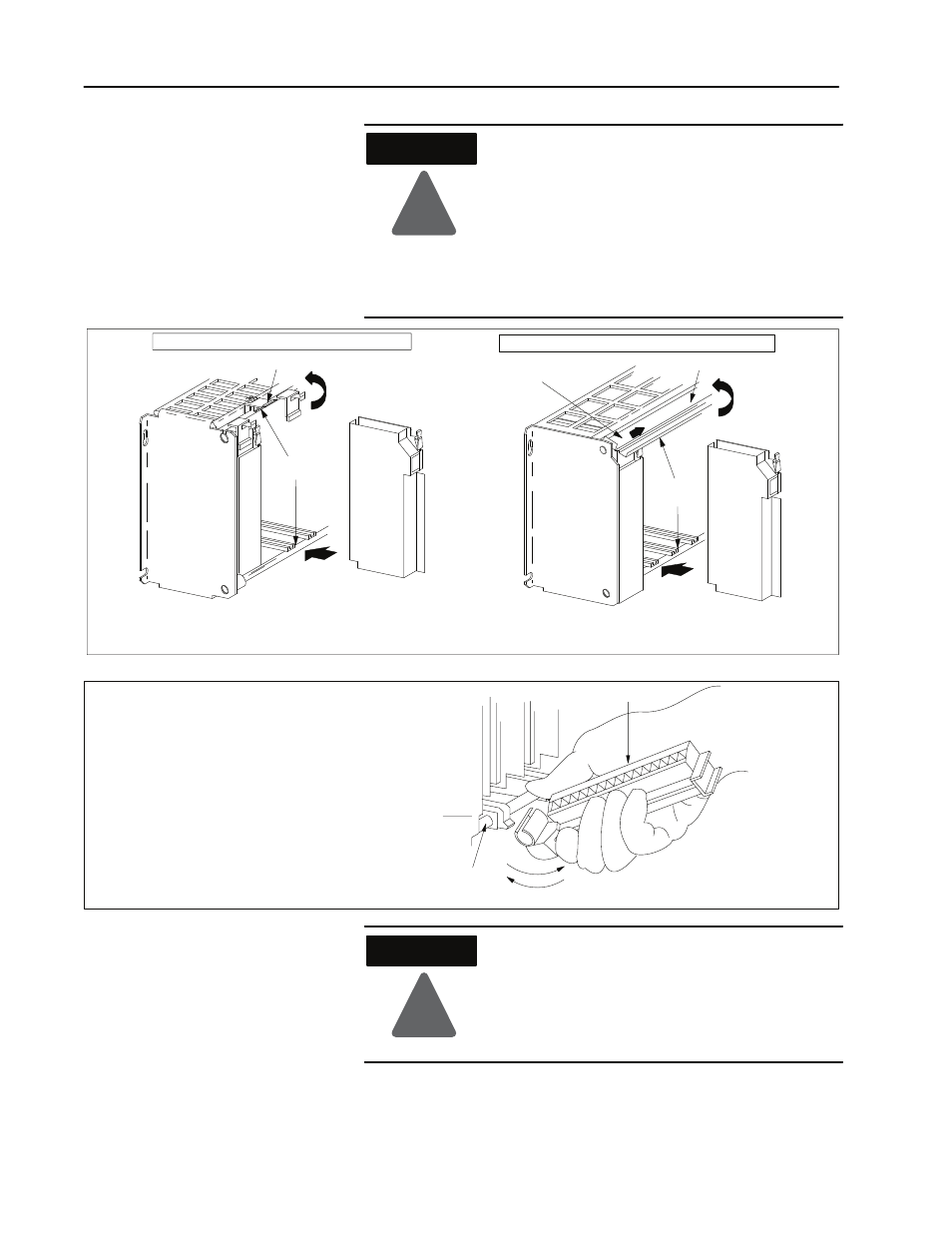
Swing the chassis locking bar down into place to secure
the modules. Make sure the locking pins engage.
1771ĆA1B, ĆA2B, ĆA3B, ĆA3B1, ĆA4B I/O chassis
1771ĆA1B, ĆA2B, ĆA3B1, ĆA4B Series B I/O chassis
locking tab
cardguides
module
module
19809
cardguides
locking bar
locking bar pin
Snap the chassis latch over
the top of the module to secure it.
17643
wiring arm
install
remove
horizontal bar
Attach the wiring arm (1771ĆWN) to the horizontal
bar at the bottom of the I/O chassis.
The wiring arm pivots upwardandconnects with
the module so you can install or remove the
module without disconnecting the wires.
1771ĆWN
!
WARNING
If you insert or remove the module while
backplane power is on, or you connect or
disconnect the wiring arm with field power
applied, an electrical arc can occur. This could
cause an explosion in hazardous location
installations. Be sure power is removed or the area
is nonhazardous before proceeding.
Install the Module and
Field Wiring Arm