Rockwell Automation 1771-OVN DC Output Mod. Installation Instructions User Manual
Page 5
DC (10–30V) Output Module
5
Publication 1771-IN036C-EN-P - July 2002
!
ATTENTION
Remove power from the 1771 I/O chassis
backplane and field wiring arm before removing
or installing an I/O module.
•
Failure to remove power from the backplane or
wiring arm could cause module damage,
degradation of performance, or injury.
•
Failure to remove power from the backplane
could cause injury or equipment damage due to
possible unexpected operation.
!
ATTENTION
A module inserted into a wrong slot could be
damaged by improper voltages connected through
the wiring arm. Use keying bands to prevent
damage to the module.
Place your module in any slot in the chassis
except the leftmost slot, which is reserved for
processors or adapters.
Observe the following precautions
when inserting or removing keys:
•
insert or remove keys with your
fingers
•
make sure that key placement is
correct
Incorrect keying or the use of a tool
can result in damage to the
backplane connector and possible
system faults.
!
ATTENTION
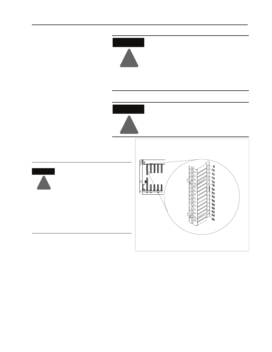
Position the keying bands in the backplane connectors to correspond to
the key slots on the module.
You can change the position of these bands if
subsequent system design and rewiring makes
insertion of a different type of module necessary.
Upper Connector
11022ĆI
I/O chassis
Place the keying bands:
- between 14 and 16
- between 32 and 34
The 1771–OVN module is a modular component of the 1771 I/O
system requiring a properly installed system chassis. Refer to
publication 1771–IN075 for detailed information on acceptable
chassis, proper installation and grounding requirements.
Initial Handling
Procedures
Keying the I/O Chassis