Rockwell Automation 1771-IFE , D17716.5.90 USER MNL. ANALOG INPUT Module User Manual
Page 57
Appendix D
Block Transfer (Mini-PLC-2 and
PLC-2/20 Processors)
D-3
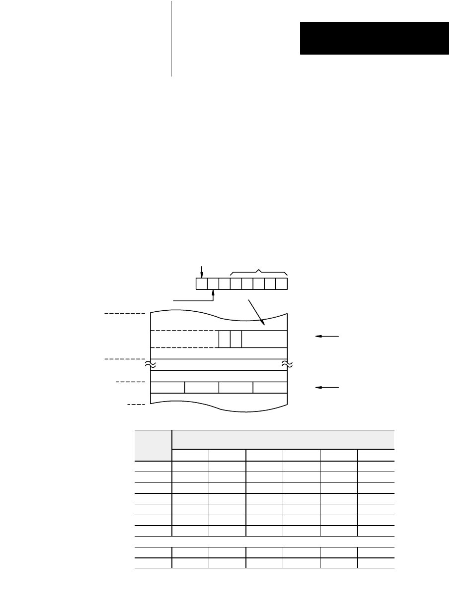
The input module transfers a specific number of words in one block length.
The number of words transferred is determined by the block length entered
in the output image table control byte corresponding to the module’s
address.
The bits in the output image table control byte (bits 00 - 05) must be
programmed to specify a binary value equal to the number of words to be
transferred.
For example, Figure D.2 shows if your input module is set up to transfer 6
words, you would set bits 01 and 02 of the lower image table control byte.
The binary equivalent of 6 words is 000110. You would also set bit 07
when programming the module for block transfer read operations. Bit 06 is
used when block transfer write operations are required.
Figure D.2
Setting Block Length (Multiple GET Instructions only)
1 0 0 0 0 1 1 0
Data Address
Contains Module
Address in BCD
Output Image Table Control
Byte Contains Read
Enable Bit and Block
Length in Binary Code
010
012
017
027
030
1
2
0
Data Table
1
R
Control
Byte
Read 6 Words
from Module
Block Transfer
Read Enable Bit
For Block
Transfer Active
Operations Only
Output Image Table
12172
Number of
Words to
Binary Bit Pattern
Lower Output Image Table Byte
Words to
Transfer
05
04
03
02
01
00
Default
0
0
0
0
0
0
1
0
0
0
0
0
1
2
0
0
0
0
1
0
3
0
0
0
0
1
1
4
0
0
0
1
0
0
5
0
0
0
1
0
1
6
0
0
0
1
1
0
: :
18
0
1
0
0
1
0
19
0
1
0
0
1
1
Setting the Block Length
(Multiple GET Instructions
only)