Grounding – Rockwell Automation 1771-IFE , D17716.5.90 USER MNL. ANALOG INPUT Module User Manual
Page 20
Installing the Input Module
Chapter 2
2-8
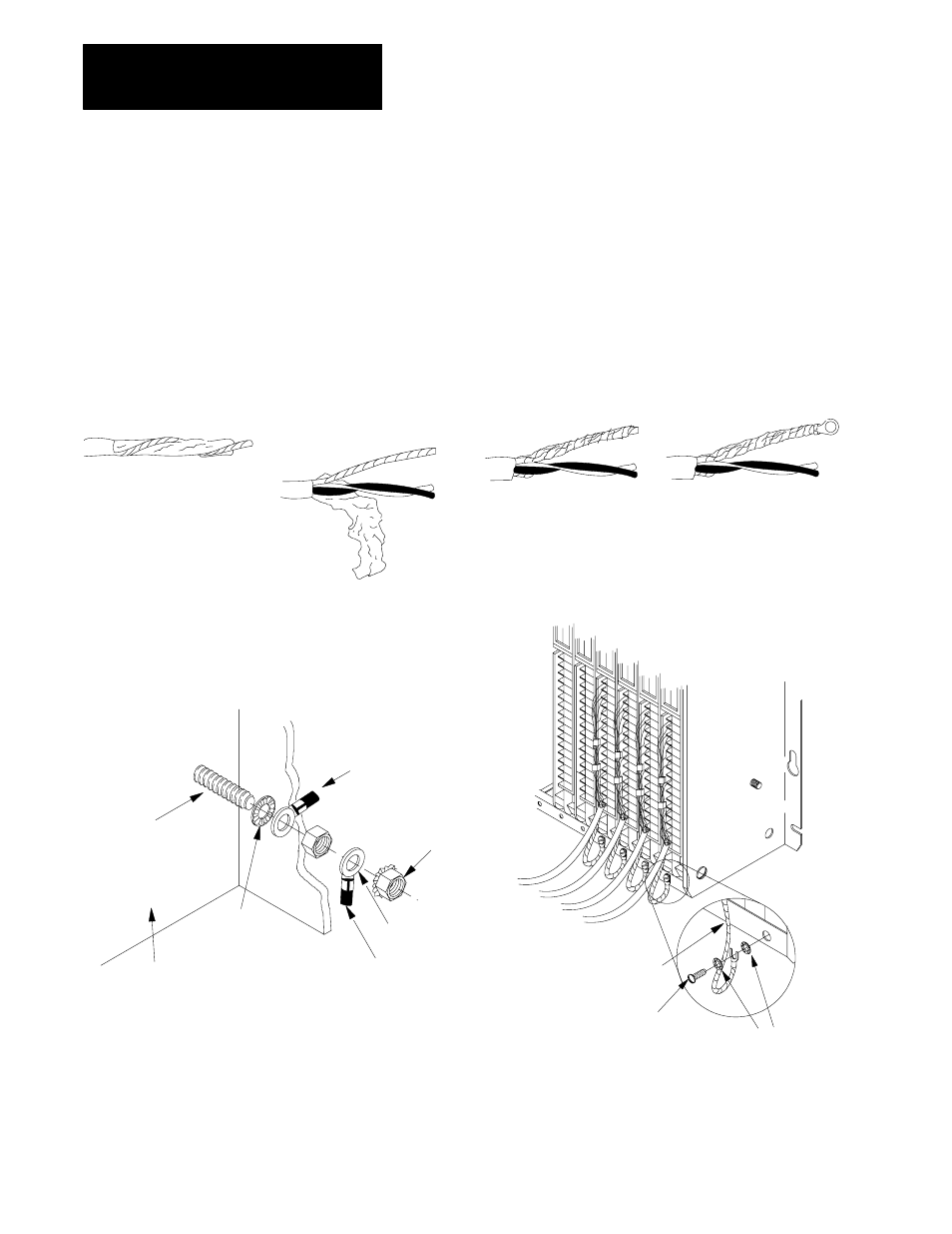
When using shielded cable wire, ground the foil shield and drain wire only
at one end of the cable. We recommend that you wrap the foil shield and
drain wire together and connect them to a chassis mounting bolt
(Figure 2.6). At the opposite end of the cable, tape exposed shield and
drain wire with electrical tape to insulate it from electrical contact.
Figure 2.6
Cable Grounding
Remove a length of cable
jacket from the Belden 8761
cable.
Pull the foil shield and bare
drain wire from the insulated
wires.
Bare drain
wire
Insulated
wires
Foil
shield
Twist the foil shield and drain
wire together to form a single
strand.
Attach a ground lug.
20104
Belden 8761 Cable
19480
When you connect grounding conductors to the I/O chassis
grounding stud, place a star washer under the first lug, then
place a nut with captive lock washer on top of each ground lug.
Grounding Stud
1
Use the cup washer if crimpĆon lugs are not used.
Chassis Ground
SingleĆpoint Grounding
Ground Lug
Nut
Ground Lug
1
Star
Washer
I/O Chassis Side Plate
Nut and Captive
Washer
ExternalĆtooth Washers
#10 ThreadĆforming screw
19923
Shield and Drain
twisted together
Shield and Drain
twisted together
Refer to Wiring and Grounding Guidelines, publication 1770Ć4.1 for additional information.
Grounding