Din rail mounting, Panel mounting – Rockwell Automation 1762-IT4 Thermocouple/mV Input Module User Manual
Page 7
MicroLogix 1200 Thermocouple/mV Input Module 7
Publication 1762-IN013B-EN-P - June 2013
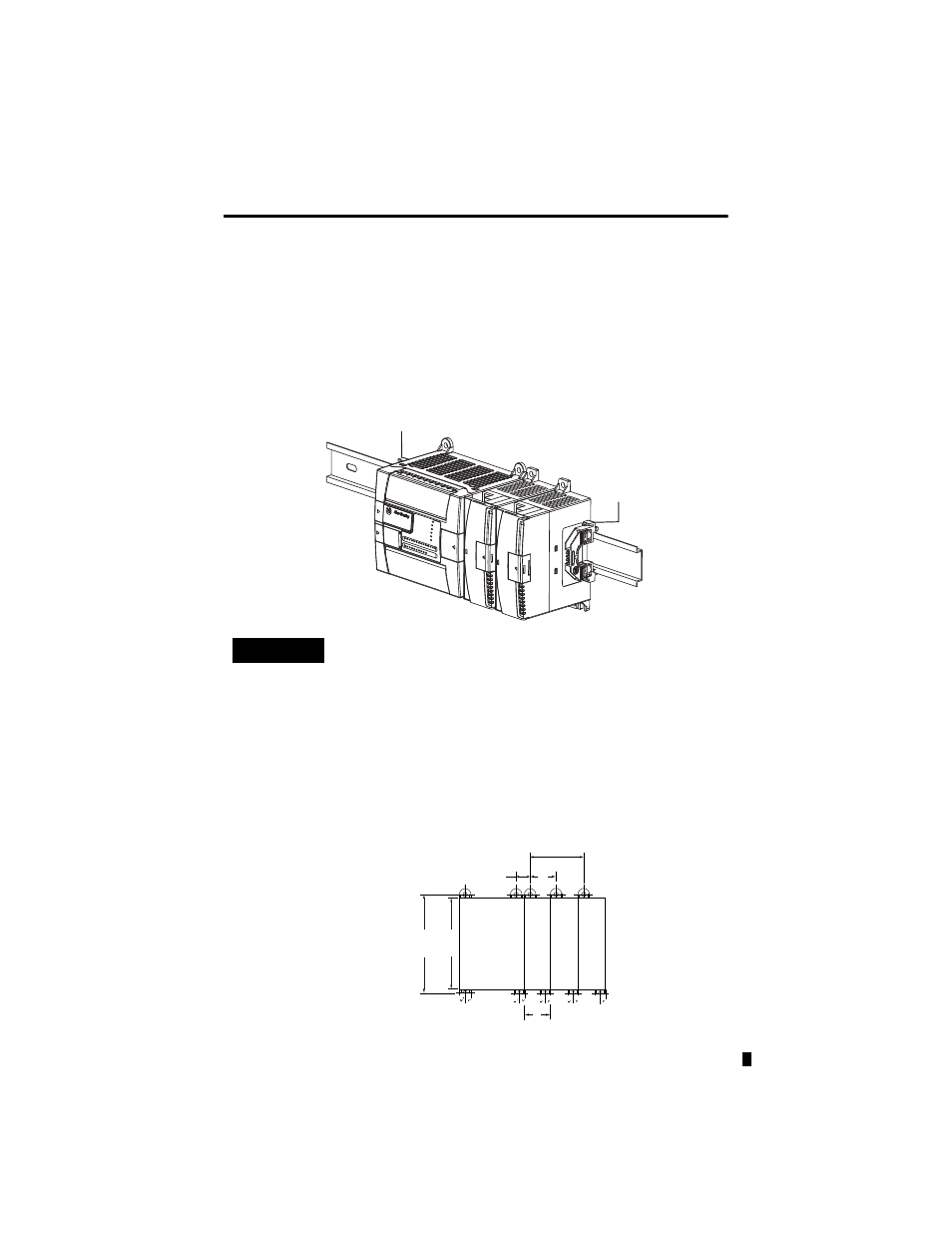
DIN Rail Mounting
The module can be mounted using the following DIN rails: 35 x 7.5 mm
(EN 50 022 - 35 x 7.5) or 35 x 15 mm (EN 50 022 - 35 x 15).
Before mounting the module on a DIN rail, close the DIN rail latch. Press the DIN rail
mounting area of the module against the DIN rail. The latch will momentarily open and lock
into place.
Use DIN rail end anchors (Allen-Bradley part number 1492-EA35 or 1492-EAH35) for
environments with vibration or shock concerns.
Panel Mounting
Use the dimensional template shown below to mount the module. The preferred mounting
method is to use two M4 or #8 panhead screws per module. M3.5 or #6 panhead screws may also
be used, but a washer may be needed to ensure a good ground contact. Mounting screws are
required on every module.
TIP
For environments with extreme vibration and shock concerns, use the
panel mounting method described below, instead of DIN rail
mounting.
End Anchor
End Anchor
90
(3.54)
100
(3.94)
40.4
(1.59)
40.4
(1.59)
14.5
(0.57)
For more than 2 modules: (number of modules - 1) x 40.4 mm (1.59 in.)
NOTE:
Hole spacing tolerance:
±0.4 mm (0.016 in.).
Mic
roLo
gix
12
00
Ex
pans
io
n I/O
Mi
cr
oL
og
ix
1
20
0
Ex
pa
ns
io
n I
/O
M
icr
oL
og
ix 1200
Ex
pans
ion I/O
Mi
cr
oL
og
ix
1
20
0