Rockwell Automation 1762-IT4 Thermocouple/mV Input Module User Manual
Page 11
MicroLogix 1200 Thermocouple/mV Input Module 11
Publication 1762-IN013B-EN-P - June 2013
Wiring Input Devices to the 1762-IT4
After the thermocouple module is properly installed, follow the wiring procedure below, using
the shielded thermocouple extension cable recommended for the type of thermocouple you are
using, or Belden 8761 for non-thermocouple applications.
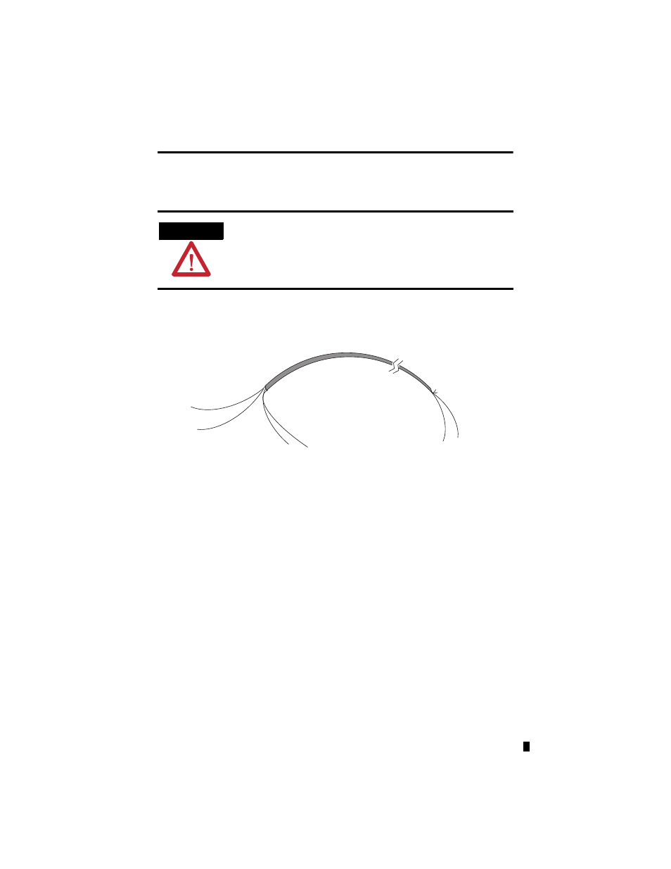
To wire your sensor to the module, follow these steps:
1. At each end of the cable, strip some casing to expose the individual wires.
2. Trim the signal wires to 2-in. lengths. Strip about 3/16 in. (5 mm) of insulation away to
expose the end of the wire.
3. At one end of the cable, twist the drain wire and foil shield together, bend them away
from the cable, and apply shrink wrap. Then earth ground at the preferred location based
on the type of sensor you are using.
4. At the other end of the cable, cut the drain wire and foil shield back to the cable and
apply shrink wrap.
5. Connect the signal wires to the module terminal block and input.
6. Repeat steps 1
…
5 for each channel on the module.
ATTENTION
Be careful when stripping wires. Wire fragments that fall into a module
could cause damage at power up. Once wiring is complete, ensure the
module is free of all metal fragments.
cable
signal wire
signal wire
drain wire
foil shield
signal wire
signal
wire
Cut foil shield and
drain wire