Modules with external fuses only – Rockwell Automation 1771-OMD AC(220V) Output Mod Installation Instructions User Manual
Page 9
9
AC (220V) Output Module Cat. No. 1771-OMD Series B
Publication 1771Ć5.26 - February 2000
5. Turn OFF all outputs to the module.
6. Turn ON power to the I/O chassis only.
7. Check that the red status indicators on the front of the module are
off (no outputs on). Make sure the red fuse blown indicator is off.
8. Turn on output device power to the field wiring arm.
9. Start with bit 00 and turn on individual outputs one at a time.
Turn off the previous output before turning on the next output.
10.If the red fuse blown indicator turns on, note which output is
faulty and trace the output wiring to the faulty device.
After correcting the fault problem, return to step 1 and begin
again.
If a faulty output can’t be located, return to step 9 and turn on two
or more outputs at the same time. Total output current should not
exceed 2A per output, or 8A total per module.
Modules with External Fuses Only
1. Turn off all power to the I/O chassis and all output device power
to the field wiring arm.
2. Pivot the wiring arm away from the module.
3. Use a continuity checker (meter in low ohms setting) to check
fuses for an open (high resistance) reading.
4. Note if the fuse is open and trace the output wiring back to the
output device.
5. Check the remaining fuses (refer to step 3).
6. After all faulty fuses are replaced and any wiring problems
solved, reposition the wiring arm on the module.
7. Turn off all outputs to the module.
8. Turn on power to the I/O chassis.
9. Check that the red status indicators on the front of the module are
off (no outputs on). Make sure the red fuse blown indicator is off.
10.Turn on output device power to the wiring arm.
ACTIVE
00
01
02
03
04
05
06
07
10
11
12
13
14
15
16
17
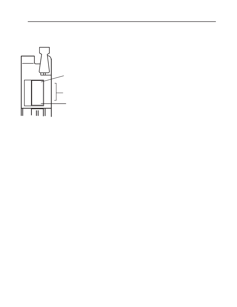
Module Active
Indicator
(green)
00 to 17
Status Indicators
(red)
FUSE
Fuse Blown
Indicator
(red)