Panel mounting – Rockwell Automation 1769-OF4CI CompactLogix 1769-OF4CI Module User Manual
Page 10
10 Compact 1769-OF4CI Isolated Analog Output Module
Rockwell Automation Publication 1769-IN075B-EN-P - August 2010
Panel Mounting
Mount the module to a panel using two screws per module. Use M4 or #8
panhead screws. Mounting screws are required on every module.
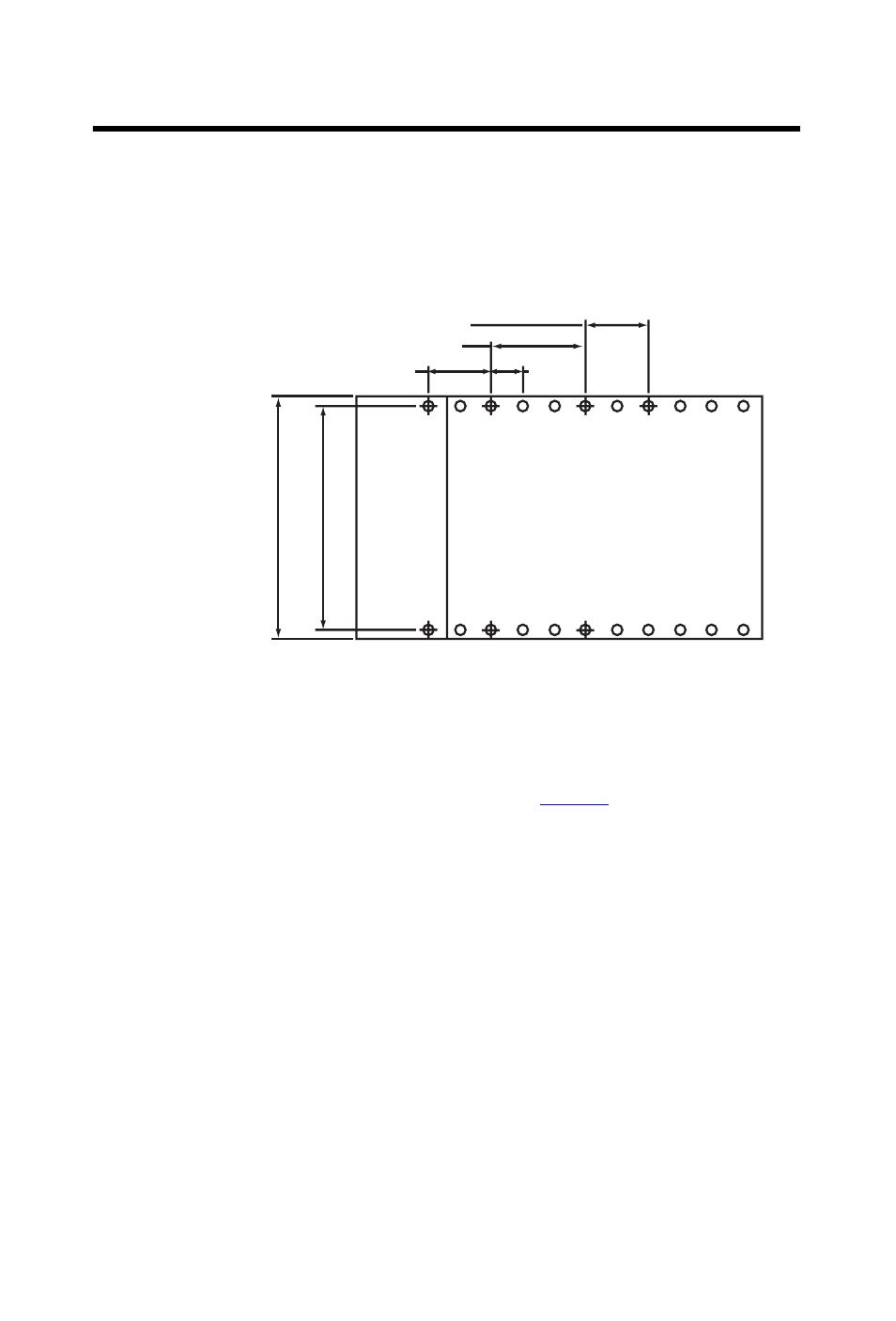
Panel Mounting Using the Dimensional Template
Panel Mounting Procedure Using Modules as a Template
The following procedure lets you use the assembled modules as a template for
drilling holes in the panel. If you have sophisticated panel mounting equipment,
you can use the dimensional template provided on
page 10
. Due to module
mounting hole tolerance, it is important to follow these procedures.
1.
On a clean work surface, assemble no more than three modules.
2.
Using the assembled modules as a template, carefully mark the center of
all module-mounting holes on the panel.
3.
Return the assembled modules to the clean work surface, including any
previously mounted modules.
4.
Drill and tap the mounting holes for the recommended M4 or #8 screw.
5.
Place the modules back on the panel, and check for proper hole
alignment.
Spacing for single-wide modules 35mm (1.378 in.)
Spacing for one-and-a half-wide modules 52.5mm (2.067 in.)
Refer to host controller documentation for this dimension.
Host Controller
Note: Overall hole spacing
tolerance:
±
0.4mm (0.016 in.).
30535-M