Rockwell Automation 1771-P4R_P6R Allen-Bradley Redundent Power Installation Instructions User Manual
Page 9
Allen-Bradley Redundant Power Supplies
9
Publication 1771-IN030B-EN-P - July 2002
The terminal block has three lines:
•
NC (Normally Closed)
•
COM (Common)
•
NO (Normally Open)
Using the normally closed side of the block will keep the relay
contacts open until unit failure (when it will close). Using the
normally open side of the relay will keep the relay contacts closed
until unit failure (when it will open).
To wire the relay, place the incoming line in the NC or NO position
and out the COM position to the load. Any spare point on an input
module can be connected and used for signaling by the relay.
To connect the wiring to the 3–terminal relay connector, proceed as
follows:
A. Strip 0.35 inches (9cm) of insulation off the wire.
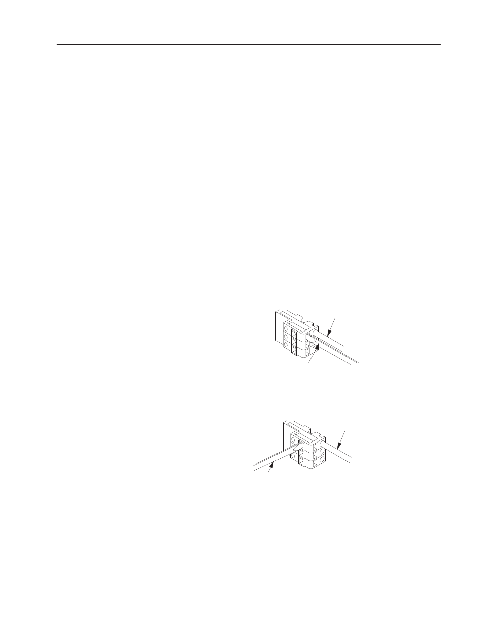
B. Spring the clip open to insert the wire, using a wedge-tipped
tool, such as a small screwdriver.
•
If you leave the terminal block plugged into the supply,
insert the tool parallel to the wire (push straight in).
Place tool here
Insert wire here
This side plugs
into the connector
on module
19966A
•
If you remove the terminal block and lay it on a flat
surface, insert the tool perpendicular to the wire (push
straight down).
Insert wire here
Place tool here
This side plugs
into the connector
on module.
19966B
C. After making the wiring connections, re-insert the terminal
block into the front plate on the processor.