Rockwell Automation 1771-P4R_P6R Allen-Bradley Redundent Power Installation Instructions User Manual
Page 11
Allen-Bradley Redundant Power Supplies
11
Publication 1771-IN030B-EN-P - July 2002
!
ATTENTION
Pay close attention to the ac GND and L1
connections when wiring the terminal block. An
error here could cause the ac power to be applied
to the chassis.
Check that the input voltage rating on the power
supply front panel agrees with the available power
source. Application of the incorrect line voltage
can cause severe power supply damage.
You can connect these wires while the terminal block is plugged into
the supply, or you can remove the terminal block to lay it on a flat
surface to connect these wires. To remove the terminal block, pull it
straight out out from the receptacle on the module.
!
WARNING
When you insert or remove the module while
backplane power is on, or you connect or
disconnect the alarm relay, ac power, or
redundancy cable with field power applied, an
electrical arc can occur. This could cause an
explosion in hazardous location installations. Be
sure power is removed or the area is nonhazardous
before proceeding.
To connect wiring to the 5–terminal ac power block, proceed as
follows:
1. Connect the power cord to the ac connector (120V or 220V) of
the power supply module.
A. Strip 0.35 inches (9cm) of insulation off the wire.
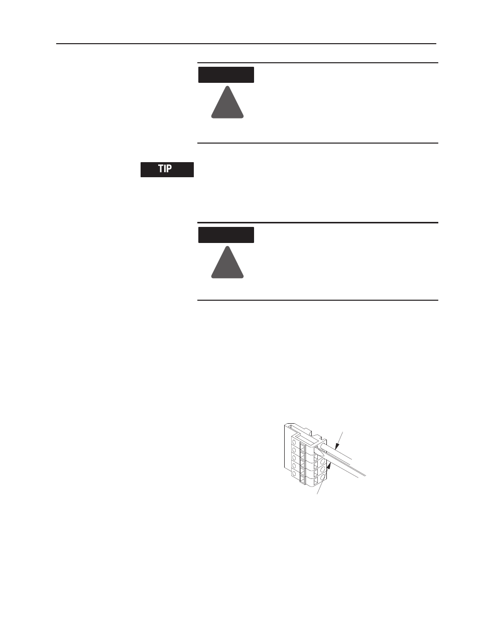
B. Spring the clip open to insert the wire, using a wedge-tipped
tool, such as a small screwdriver.
•
If you leave the terminal block plugged into the supply,
insert the tool parallel to the wire (push straight in).
Place tool here
Insert wire here
This side plugs
into the connector
on module
19966
"