Wiring to a 1794 tb2 or tb3 terminal base unit, Wiring to a 1794 tbn or tbnf terminal base unit, Wiring to a 1794ćtbn or ćtbnf terminal base unit – Rockwell Automation 1794-IA8 INSTL INST 8 INPUT MODULE User Manual
Page 3: Ab c
3
120V ac FLEX I/O 8 Input Module (Cat. No. 1794ĆIA8)
Publication 1794Ć5.9
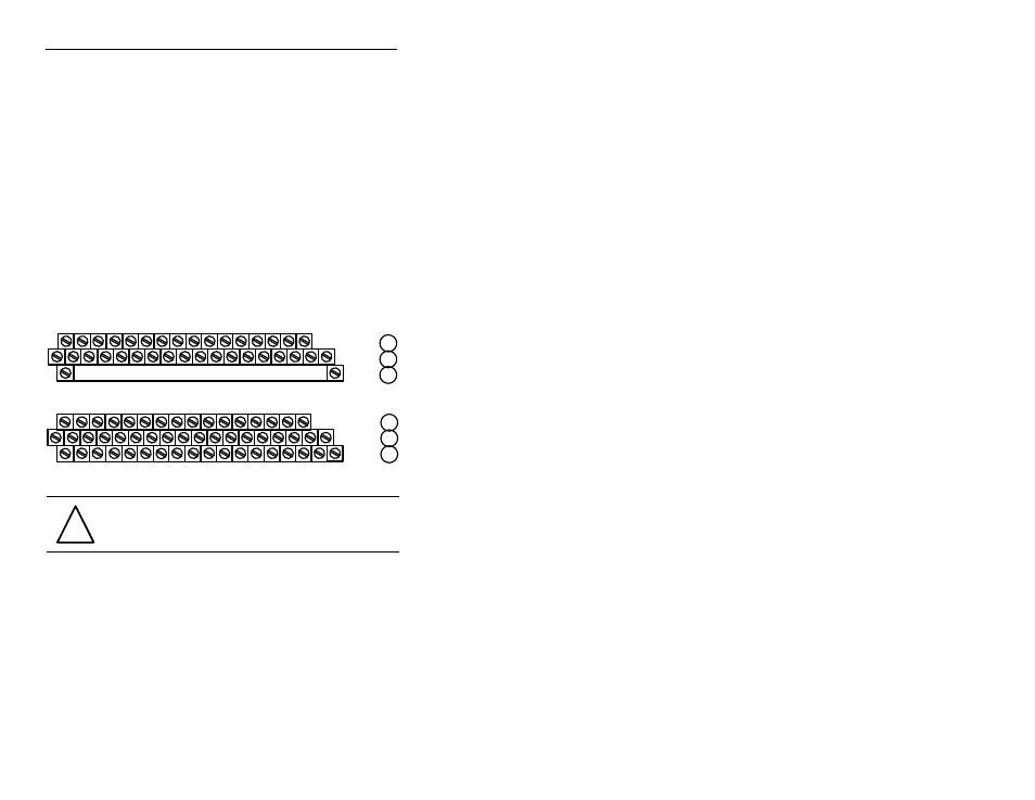
Wiring to a 1794ĆTB2 or ĆTB3 Terminal Base Unit
1. Connect individual
input
wiring to numbered terminals on the 0–15
row (A) as indicated in the table below.
1.
Connect the associated input wiring to the corresponding odd numbered
terminal on row (A) (1794-TB2) or the associated terminal on row (C)
(1794-TB3) for each input as indicated in the table below. (Odd numbered
terminals on row A and terminals C-34 thru C-51 are internally connected
together.)
2. Connect 120V ac L1 to terminal 34 on the 34–51 row (C).
3. Connect 120V ac common L2 to terminal 16 on the 16–33 row (B).
4. If continuing power to the next terminal base unit, connect a jumper
from terminal 51 (120V ac L1) on this base unit to terminal 34 on the
next base unit.
5. If continuing common to the next terminal base unit, connect a jumper
from terminal 33 (120V ac common L2) on this base unit to terminal
16 on the next base unit.
1
51
34
17
18
19
20
21
22
23
24
25 26
27
28
29
30
31
32
33
0
1
2
3
4
5
6
7
8
9
10
11
12
13
14
15
16
0 -15
34-51
16-33
1 2 3 4 5 6 7 8 9 10 11 12 13 14 15
0
1794ĆTB2
A
B
C
17
18
19
20
21
22
23
24
25 26
27
28
29
30
31
32
33
0
1
2
3
4
5
6
7
8
9
10
11
12
13
14
15
16
1 2 3 4 5 6 7 8 9 10 11 12 13 14 15
0
35
36
37
38
39
40
41
42
43 44
45
46
47
48
49
50
51
34
1794ĆTB3
0 -15
34-51
16-33
A
B
C
!
ATTENTION:
Total current draw through the terminal base
unit is limited to 10A. Separate power connections to the terminal
base unit may be necessary.
Wiring to a 1794ĆTBN or ĆTBNF Terminal Base Unit
1.
Connect individual input wiring to the even numbered terminals on row (B) as
indicated in the table below.
2.
Connect the associated input wiring to the corresponding odd numbered
terminal on row (C) for each input as indicated in the table below.
6. Connect 120V ac (L1) to terminal 34 on row (C).
7. Connect 120V ac common (L2) to terminal 16 on row (B).