Digital output terminals – Rockwell Automation 1753-IB8XOB8 GuardPLC 8-Digital Inputs and 8-Digital Outputs Module Installation Instructions User Manual
Page 14
14 GuardPLC 8-Digital Inputs and 8-Digital Outputs Module
Publication 1753-IN010A-EN-P - October 2005
The negative-switching outputs DO4- and DO8- can supply up to 1 A at the
maximum ambient temperature of 60 °C (140 ° F), 2 A at an ambient temperature of
40 °C (104 °F).
With an overload, one or all of the outputs are turned off. When the overload is
eliminated, the outputs are activated again.
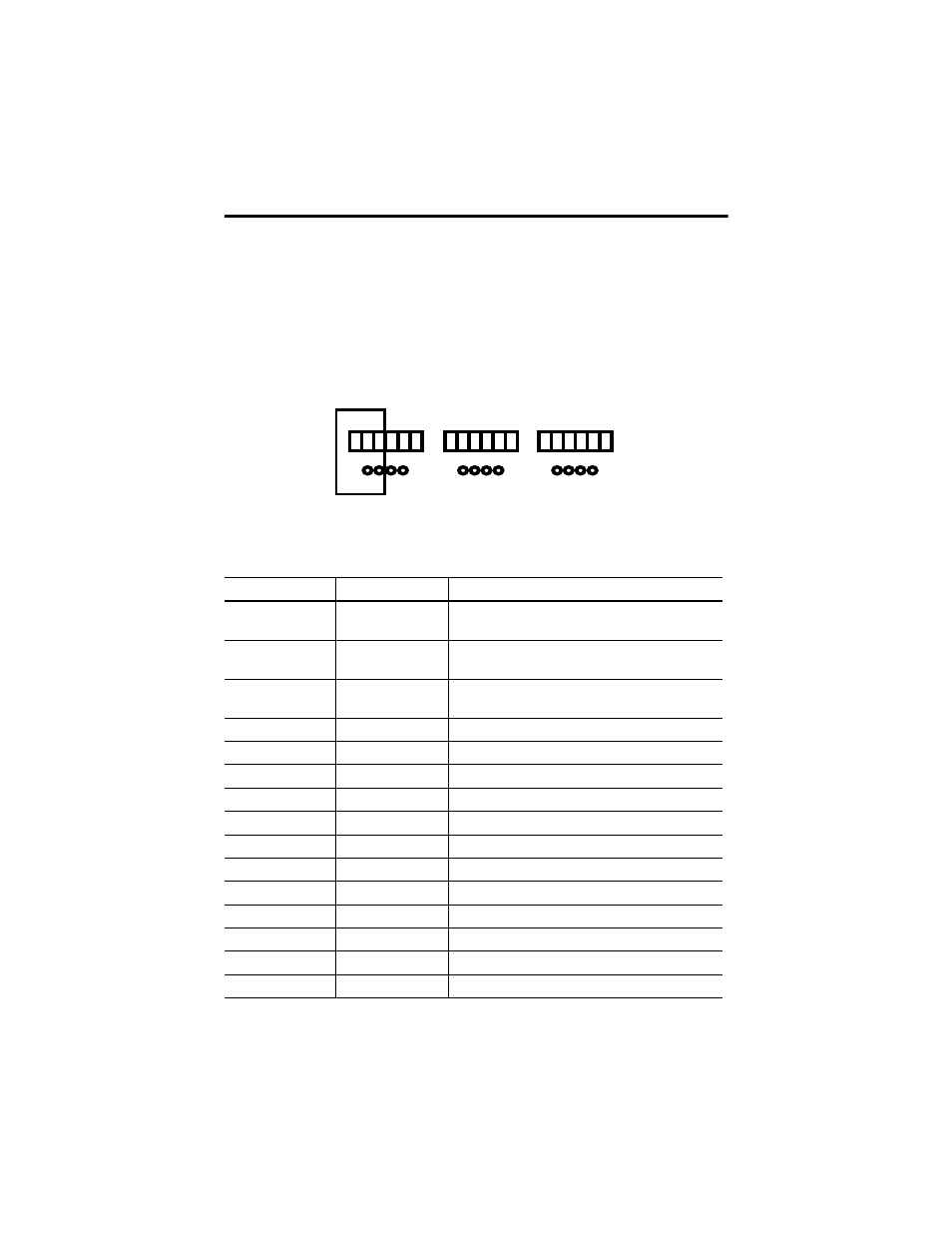
Digital Output Terminals
See page 18 for the appropriate wire size. Digital outputs are connected to the
following terminals:
Terminal Number
Designation
Function
4
4-
Negative-switching digital output 4 (for increased load or
bi-polar output)
5
8-
Negative-switching digital output 8 (for increased load or
bi-polar output)
6
S+
Reference pole for negative-switching digital outputs
(short circuit protected)
7
L-
Reference pole for positive-switching digital outputs
8
1
Digital output 1
9
2
Digital output 2
10
3
Digital output 3
11
4
Digital output 4 (for increased load or bi-polar output)
12
L-
Reference pole for positive-switching digital outputs
13
L-
Reference pole for positive-switching digital outputs
14
5
Digital output 5
15
6
Digital output 6
16
7
Digital output 7
17
8
Digital output 8 (for increased load or bi-polar output)
18
L-
Reference pole for positive-switching digital outputs
1
L-
L-
DO
2 3 4+
(2A)
7
8
9
10 11 12
7
8
9
10 11 12
5
L-
L-
DO
6 7 8+
(2A)
13 14 15 16 17 18
13 14 15 16 17 18
1
L-
S+
PO
2 4- 8-
(2A)
1
2
3
4
5
6
1
2
3
4
5
6
DO-