Installation, Chapter, Mounting – Rockwell Automation 1502 400 Amp Medium Voltage Contactor (Series D) User Manual
Page 19
Installation
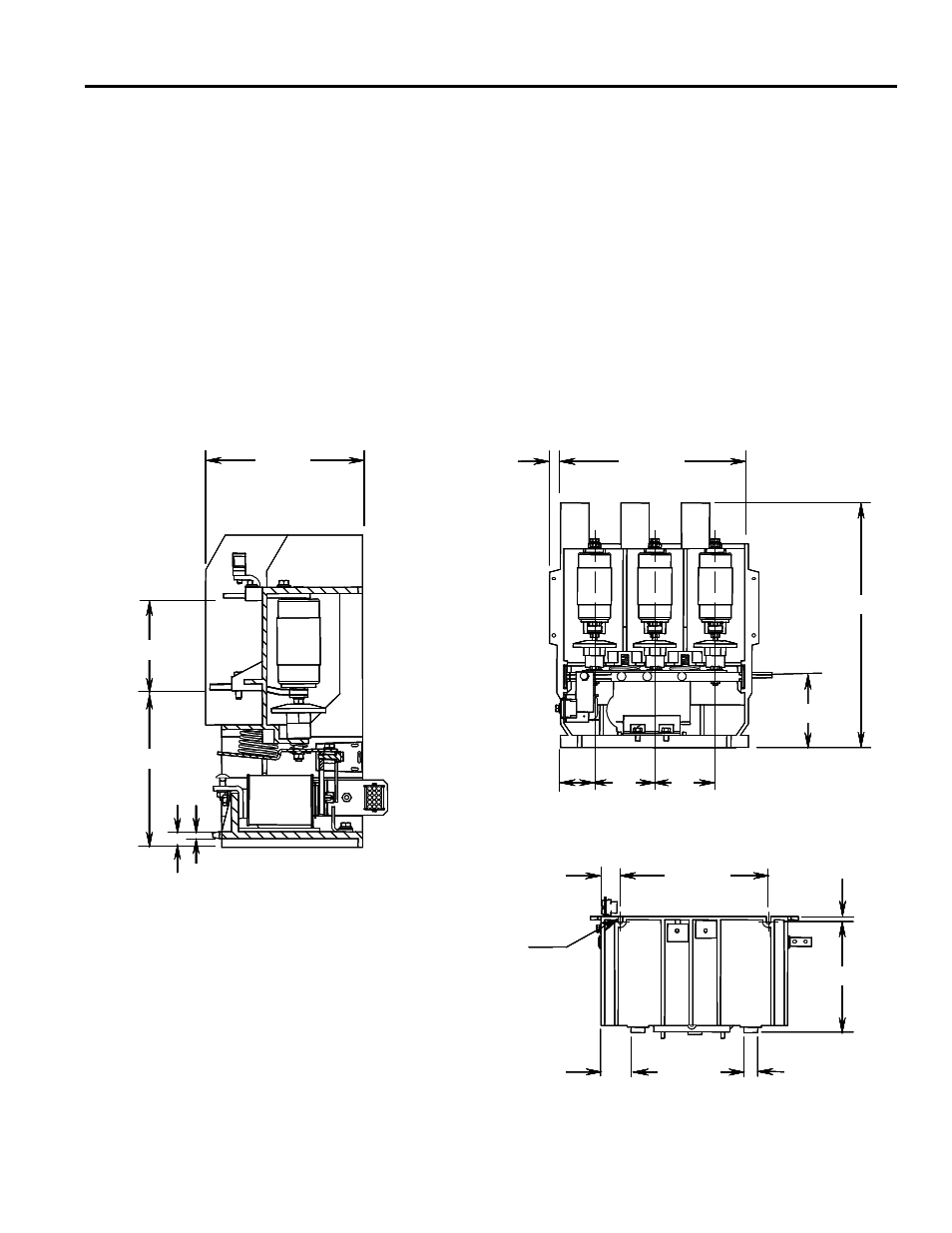
Mounting
The electrically held and the mechanically latched contactors are fixed
mounted (bolted down) in the controller’s cabinet. Two retaining tabs at the
rear of the contactor’s molded base can be used for mounting. The two
mounting slots at the front of the contactor’s molded base are used to secure
the contactor with 1/4-in. bolts. The appropriate mounting configuration is
provided inside the power cells of Allen-Bradley controllers. If the contactor
is supplied as a OEM component for installation in a custom application, refer
to the dimensional information in Figure 3.1. If the contactor is to be mounted
in an enclosure designed by an OEM, make sure there is a minimum of 3 inches
(76 mm) of air space between live parts (terminals and vacuum bottles) and
any part of the enclosure.
Bottom View
0.281 [7] wide slots
10.50 [267]
1.36 [35]
2.12 [54]
8.00 [203]
0.98 [25]
7.87 [200]
0.37 [9]
8.64 [219]
4.96 [126]
8.53 [217]
0.91 [23]
0.37 [9]
Cut-away View
0.75 [19]
3.15
[80]
4.25
[108]
Front View
13.22 [336]
4.25
[108]
5.00 [127]
17.24 [438]
Note:
Dimensions shown in inches [mm].
Bottom View
0.281 [7] wide slots
10.50 [267]
1.36 [35]
2.12 [54]
8.00 [203]
0.98 [25]
7.87 [200]
0.37 [9]
Bottom View
0.281 [7] wide slots
10.50 [267]
1.36 [35]
2.12 [54]
8.00 [203]
0.98 [25]
7.87 [200]
0.37 [9]
0.281 [7] wide slots
10.50 [267]
1.36 [35]
2.12 [54]
8.00 [203]
0.98 [25]
7.87 [200]
0.37 [9]
8.64 [219]
4.96 [126]
8.53 [217]
0.91 [23]
0.37 [9]
Cut-away View
8.64 [219]
4.96 [126]
8.53 [217]
0.91 [23]
0.37 [9]
Cut-away View
0.75 [19]
3.15
[80]
4.25
[108]
Front View
13.22 [336]
4.25
[108]
5.00 [127]
17.24 [438]
0.75 [19]
3.15
[80]
4.25
[108]
Front View
13.22 [336]
4.25
[108]
5.00 [127]
17.24 [438]
Note:
Dimensions shown in inches [mm].
Figure 3.1 – Contactor Mounting Details
Chapter
3
1502-UM050D-EN-P – June 2013